
Random Quote Board
An Overview of SDRuno SDRconnect
I had been working for quite some time on a post about SDRuno. Frankly, it was going to be quite scathing on its user interface. While the radio itself is quite good, SDRuno's controls left a lot to be desired.
A lot.
Then I discovered that SDRplay Ltd has a new program, SDRconnect. I'm going to talk about that, instead.
As stated on SDRplay's website on the development of SDRconnect:
A little over a year ago, we decided that to re-develop SDRuno as a true cross-platform SDR solution was practically unfeasible and instead commenced the development of a completely new, ‘ground up’ solution which we chose to call SDRconnect to distinguish it from SDRuno, which itself will continue to be supported on Windows.
I can tell you that they've succeeded in vastly improving their software. It has been greatly simplified, and thankfully so. There are still some issues with the software (it is in beta form, after all), but I'm willing to give them the benefit of the doubt. They also state:
The first release of SDRconnect will NOT encompass all of the functionality that we intend for this software. Instead, there will be a range of more frequent updates than people will have experienced with SDRuno.
On with the review.
SDRuno vs SDRconnect
I was originally going to review the Windows-only SDRuno. When I switched to SDRconnect, I was going to review the Windows version, as well. Unfortunately, the Windows version is waaaaaay too buggy. It crashes more often than it runs. Fortunately, SDRconnect has been made cross-platform compatible. This includes a version for Linux, which I've loaded onto my system running Linux Mint 21.2. It has been working relatively well on Mint. Probably because Mint is based on Ubuntu.
I was also going to do this as a video. Recording video on Linux is, uh, less than optimal, however, and since SDRconnect on Windows crashes so much, this will still be a static blog post. If SDRconnect becomes more reliable on Windows, then I'll relook at making this as a video.

Overview
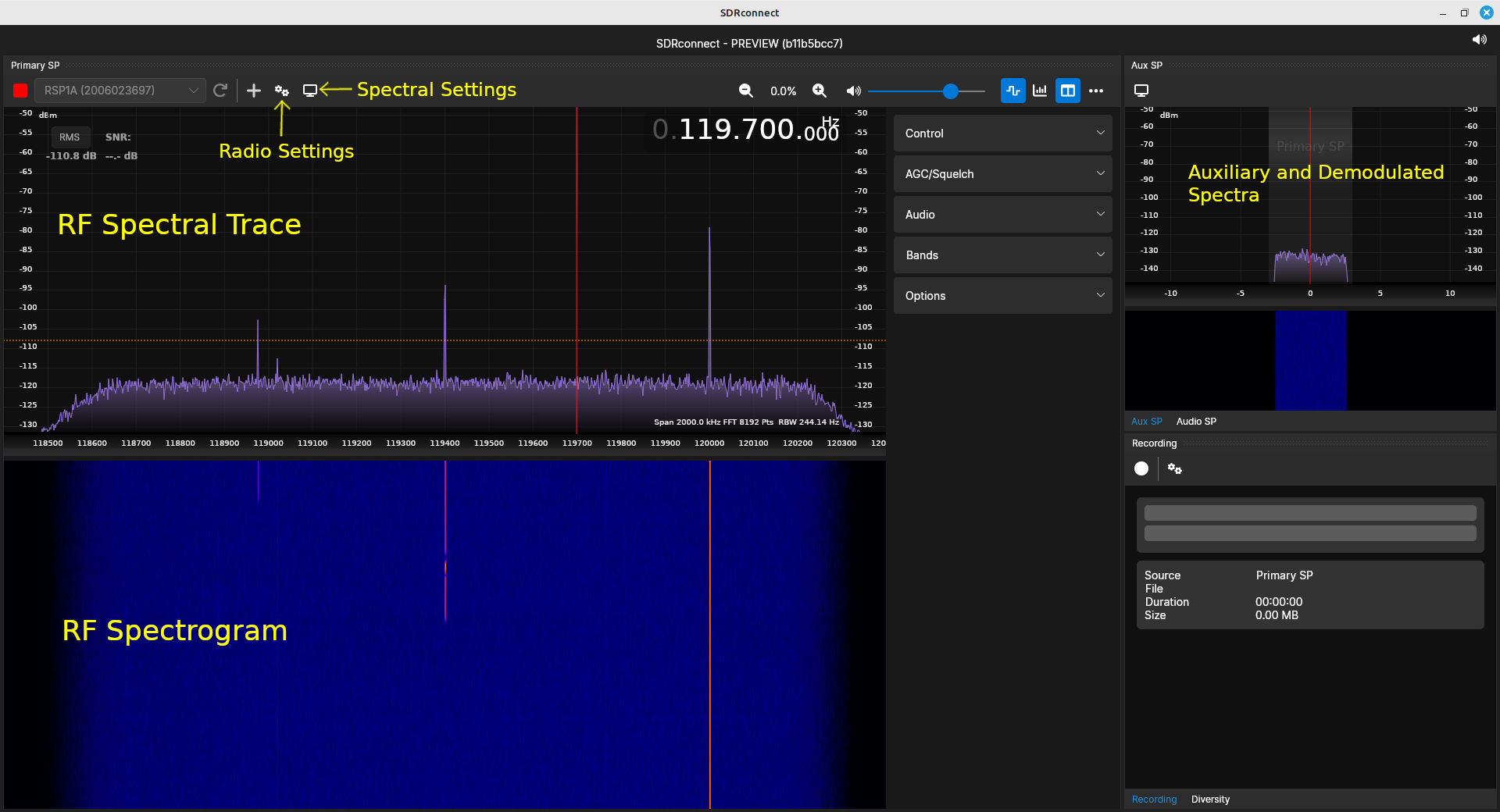
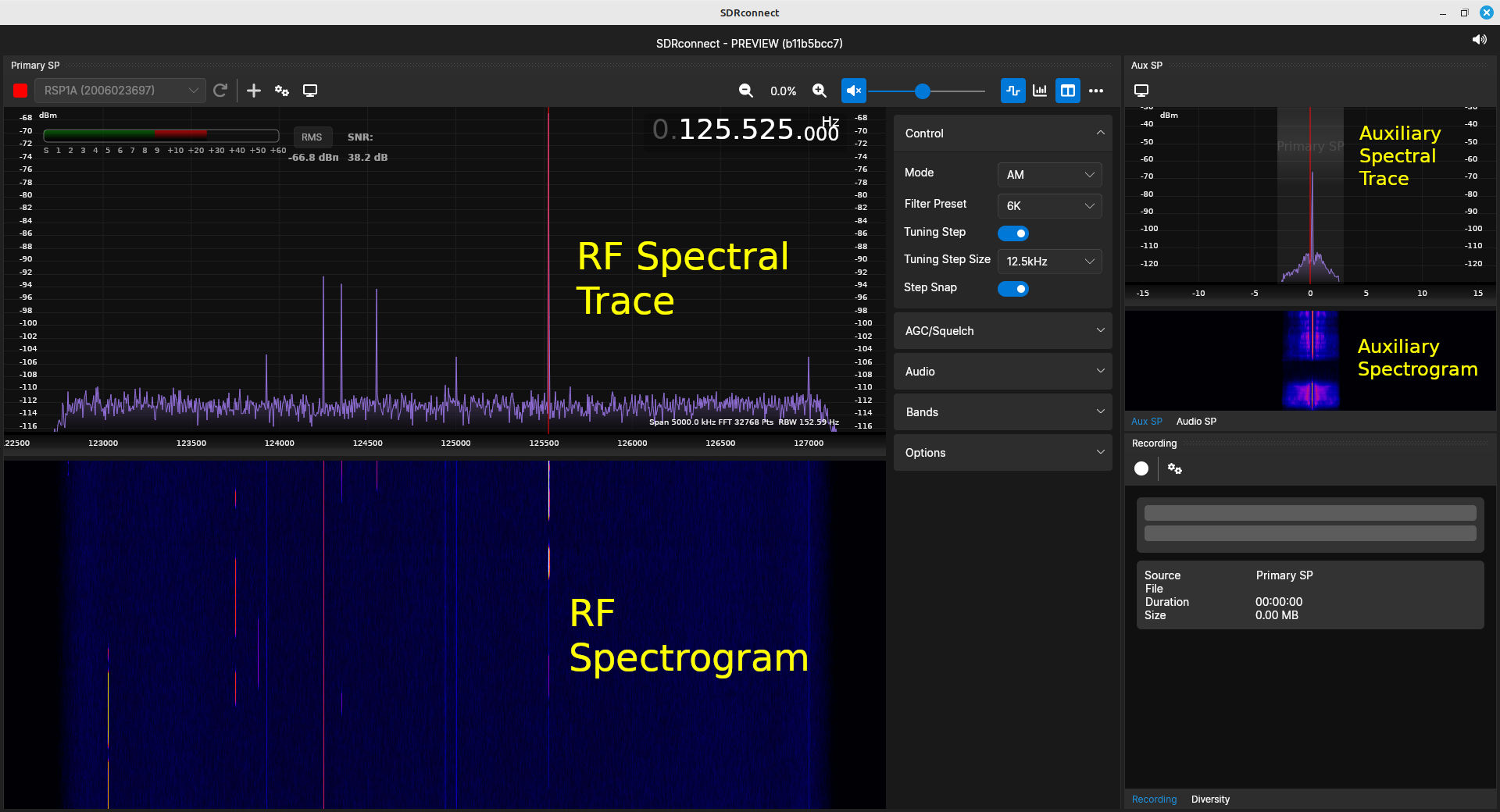
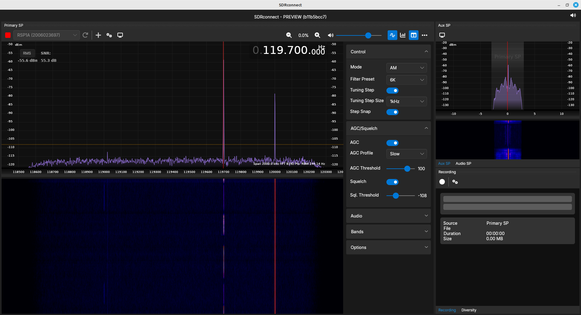
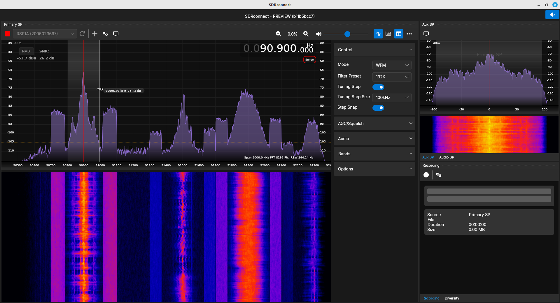
I think the best way to describe this program is as a receiver with very nice spectral displays. I could actually say that about most SDR programs. SDRconnect stands out due to its desire to fill the niche of dealing with amateur radio signals. The main components are shown below.
SDR Functions
I break down SDR software functionality into different categories. These are:
- Radio controls
- Spectral displays
- Demodulators
- Demodulation processing
- Recording
Radio Controls
Radio controls concern the basic controls of the hardware itself. This includes:
- selecting the antenna input (for those radios that have more than one)
- setting the center frequency
- adjusting the various gains (RF, IF and baseband)
- setting the sample rate
Selecting the Antenna Input
My radio is the RSP1A. It only has one antenna input. The SDRplay RSPduo, however, has two inputs. Using such a radio would mean having to choose which input to use.
Setting the Frequency
In general, SDR programs provide four ways to set the frequency. These are:
- Type in the frequency. This was one, possible method with SDRuno. SDRplay has not added this to SDRconnect yet. Since it's still in "beta", it's possible it may be added in the future.
- Change the digits one at a time. This uses the mouse to either roll the mouse wheel or click the mouse button to change the value of any digit either up or down. This appears to be one of the primary method for changing the frequency in SDRconnect.
- Use the mouse on the spectral display. One method is to click on the spectrum where you want to set the frequency. The other method is to put the cursor over the spectrum, then roll the mouse wheel. SDRconnect uses both of these methods. The nice thing about using this method is that SDRconnect (just as SDRuno did) only uses a step size. This means the frequency will be directly on a channel frequency, or close enough to require very little adjustment.
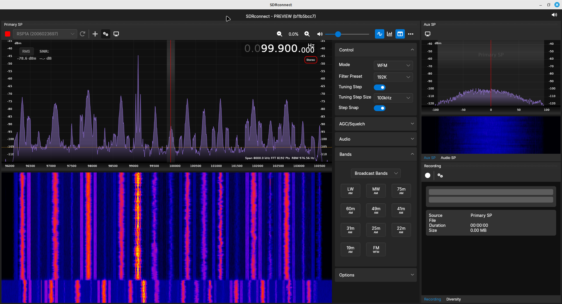
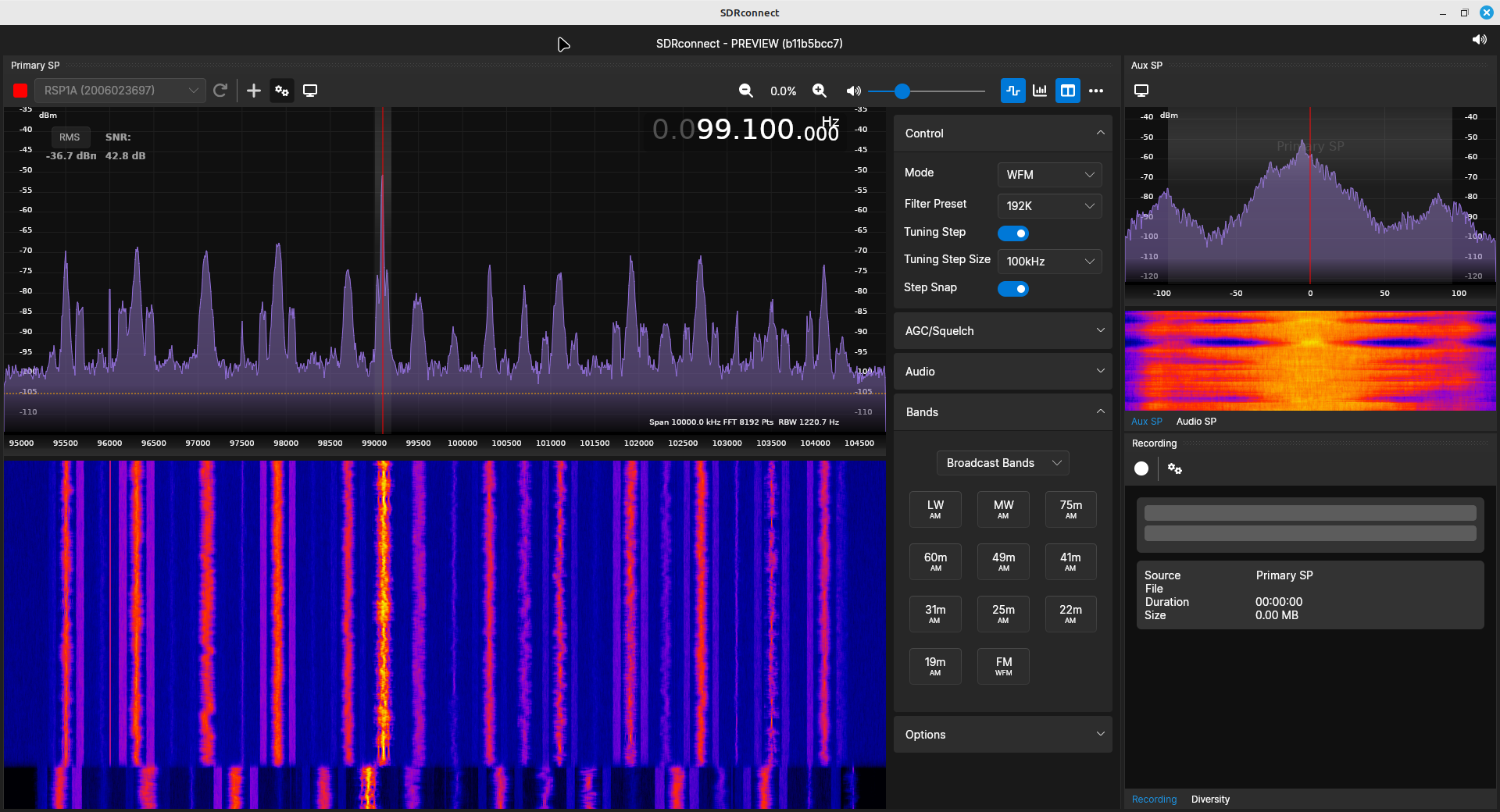
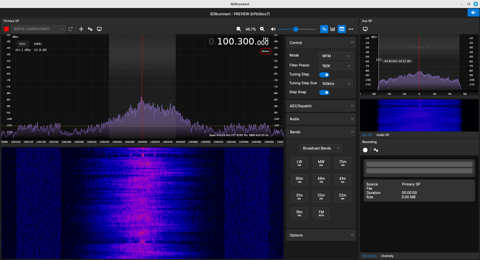
- Using presets. SDRconnect provides some presets for different frequency bands. They are all listed under the section called, appropriately enough, "Bands". These settings will set the hardware center frequency, the sample rate, and the demodulator. Not all of these settings are correct, however. For example, the citizen's band (CB) set the demodulator to NFM (narrowband FM). CB transmissions are double sideband - full carrier (DSB-FC) AM. It also lists NOAA as AM. It appears that this band is for NOAA's National Weather Radio (NWR). Those transmissions are NFM.
There's another general aspect of what we calling "tuning the frequency of the SDR". What, precisely, are you tuning? This revolves around two possible aspects that are being tuned. These are:
- Hardware center frequency: This refers to how the oscillators within the radio hardware are set such that center of the spectral display corresponds to the set center frequency. There appears to be only one way to specifically set the hardware center frequency in SDRconnect. That's using the "Bands" window. When you select a specific band, it sets the hardware center frequency to a specific center frequency. Unfortunately, there's no way to determine what that frequency will be.
- Demodulator center frequency: This refers to the software-based frequency offset added to the hardware center frequency. This will tune the software-based demodulator such that any signal at that frequency will be ready to be filtered and demodulated.
SDRconnect uses the latter method. Setting the frequency in SDRconnect will set the frequency of the demodulator. It only changes the hardware frequency if the set frequency is outside of the current spectral display.
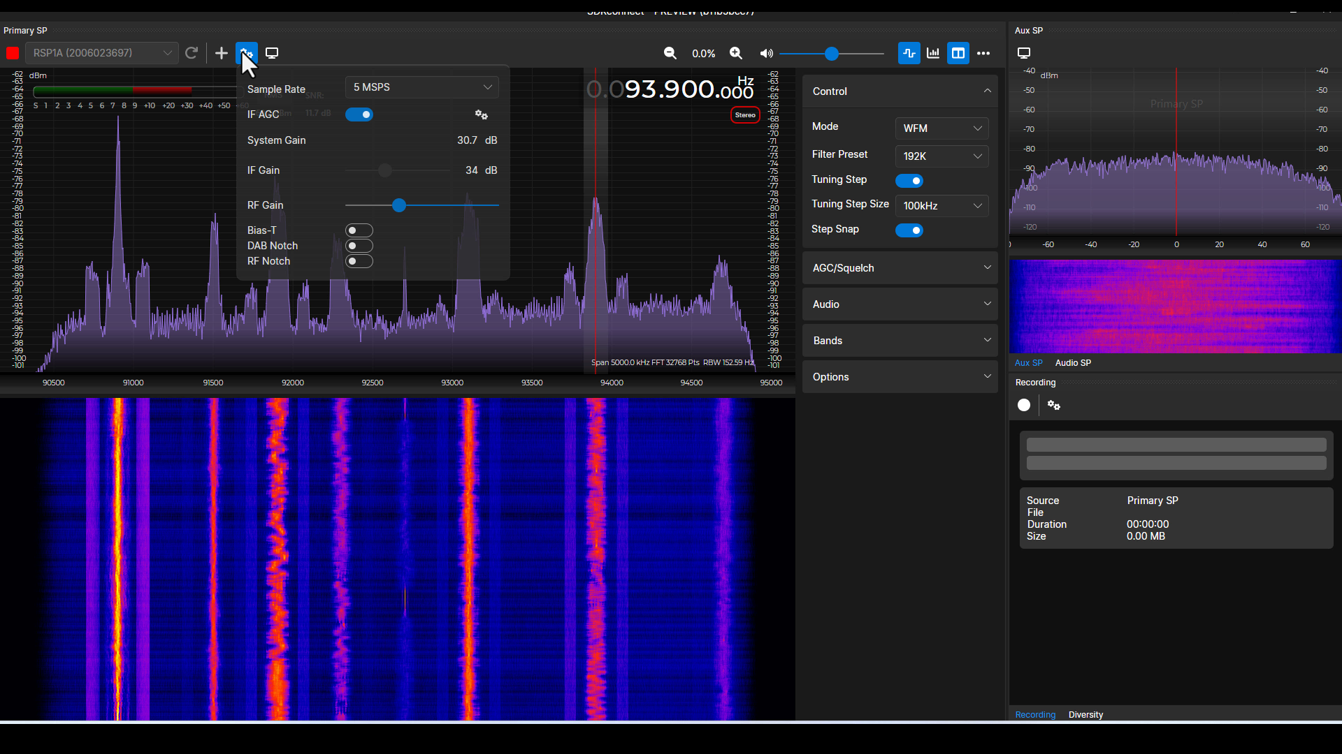
Setting the Gain
The signals coming off of antennas are typically quite weak. They require amplification. SDRs all have amplifiers. There will be amplifiers throughout the radio. Three areas where the radio may have adjustable amplifiers are:
- the low noise amplifier or LNA. This is the first amplifier after the antenna, and will ensure that there is enough signal strength for the remainder of the radio. Pretty much every SDR has the ability to adjust the gain of this amplifier.
- an amplifier within the various intermediate frequency (IF) stages. These amplifiers adjust the gain as the signal is being mixed and filtered.
- an amplifier at baseband. This is typically not done in the SDR, as "baseband" typically means "demodulated". All demodulation is done in software; baseband amplification would also occur in software, not the SDR itself. However, a radio might refer to amplification in the last, low frequency IF stage as "baseband". NOTE: This is a guess on my part.
The RSP1A has adjustable amplifiers at two stages: RF (the LNA at the front end of the RF hardware) and IF. The point of adjusting the gain of each amplifier is to ensure that the signal level is maximized, but without going past what the remainder of the system, such as the digitizer, can handle. In other words, too much of a good thing is still too much.
Fortunately, SDRconnect provides simple controls for the various gain values. Normally, an automatic gain control (AGC) is used to control all of the various gain values. SDRconnect provides AGC for the IF stages; it leaves the RF stage amplification to the user. The good thing about this is that it makes it difficult to overload the system. If the RF stage is increased, the IF stage will be adjusted to compensate and ensure the overall gain is maximized for system performance. I've tried it out using different bands, and it appears to work quite well.
Further, SDRconnect provides a simple alert if the amplification is too high. It will show an alert of "Overload". Such an overload means that either the IF or RF gain values need to be adjusted. You'll typically only see this if AGC is turned off.

Setting the Sample Rate
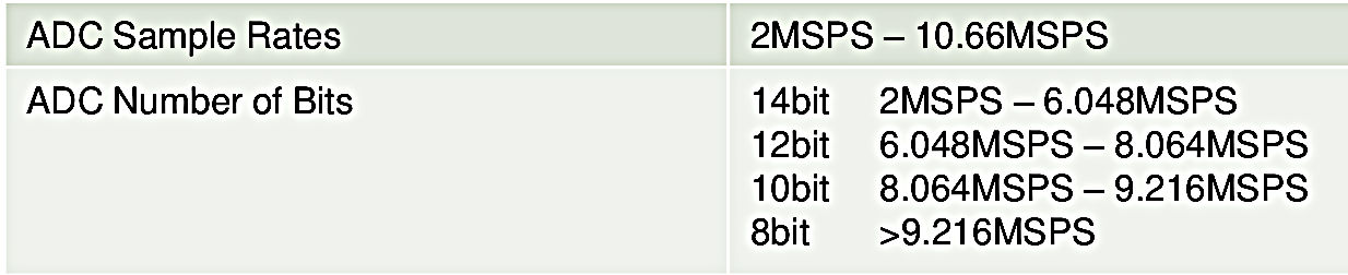
Setting the sample rate on a SDRplay SDR affects more than just the available bandwidth. With my RSP1A, it also affects the available number of bits in the ADC and whether the spectra is "low IF" or "zero IF".
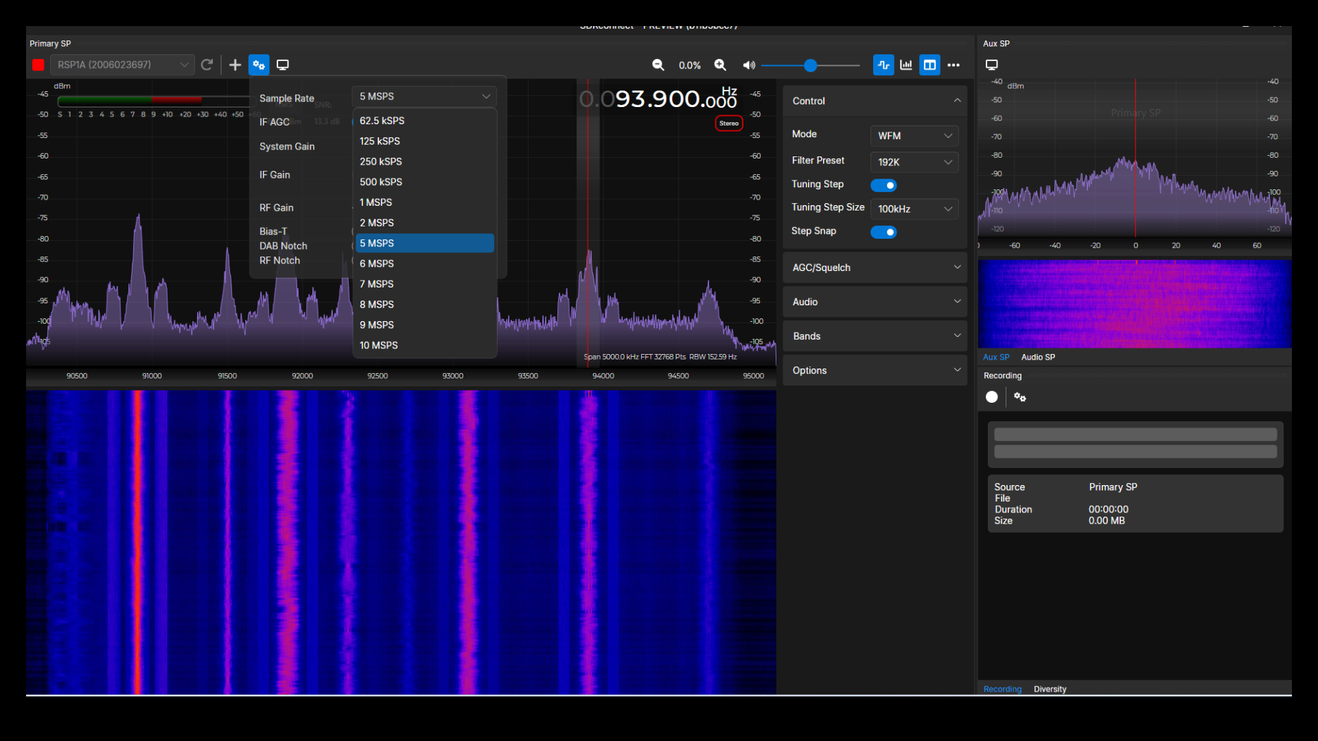
Using a RSP1A, the available sample rates are 62.5 kHz up to 10 MHz. Unlike every other SDR, however, the sample rate directly affects the ADC number of bits. The number of bits can change from 14 bits (for sample rates below roughly 6 MHz) down to 8 bits (for sample rates above 9.2 MHz).
SDRplay makes use of two types of IF. These are "low IF" and "zero IF". SDRuno had all kinds of settings to choose between the two. SDRconnect has simplified this greatly.
- Low IF: For any sample rate of 2 MHz or less, the system will use "low IF". That means no LO feedthrough to worry about. Also note that all of the sample rates less than 2 MHz is the 2 MHz decimated by factors of 2. The lowest sample rate, 62.5 kHz, is 2 MHz decimated by 32 (25).
- Zero IF: Sample rates of 5 MHz and higher will be "zero IF", with a LO feedthrough signal present.
You can set the sample rate under the same window as setting the gain. The RSP1A filters the sampled bandwidth to roughly 83% of the sample rate.
Spectral Displays
SDRconnect provides the following spectral displays:
- A RF spectral trace and spectrogram: These display available signals, and allow the user to tune to them by simply clicking on them with the computer cursor. The spectrogram is useful for seeing how active a particular frequency is over time.
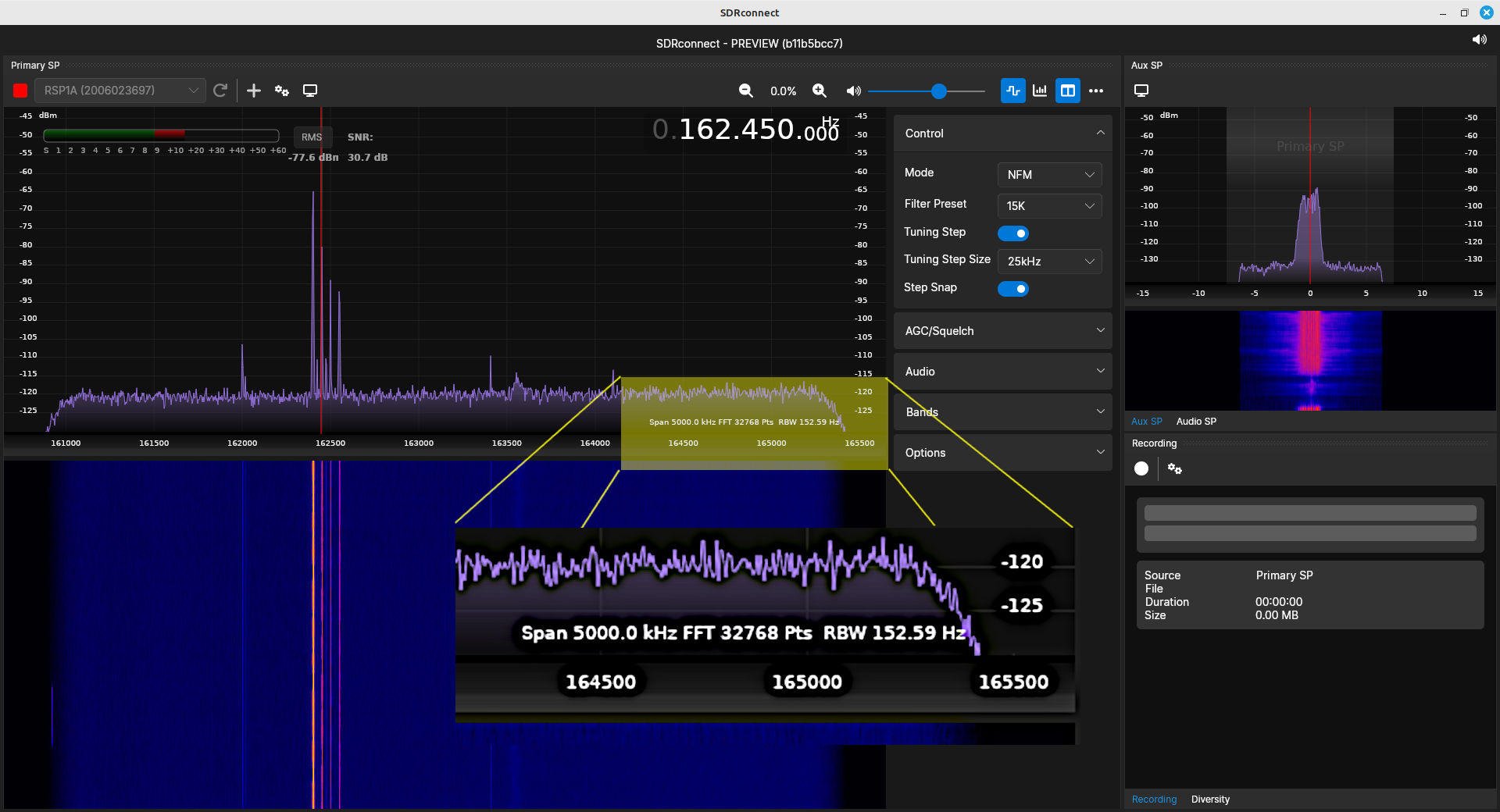
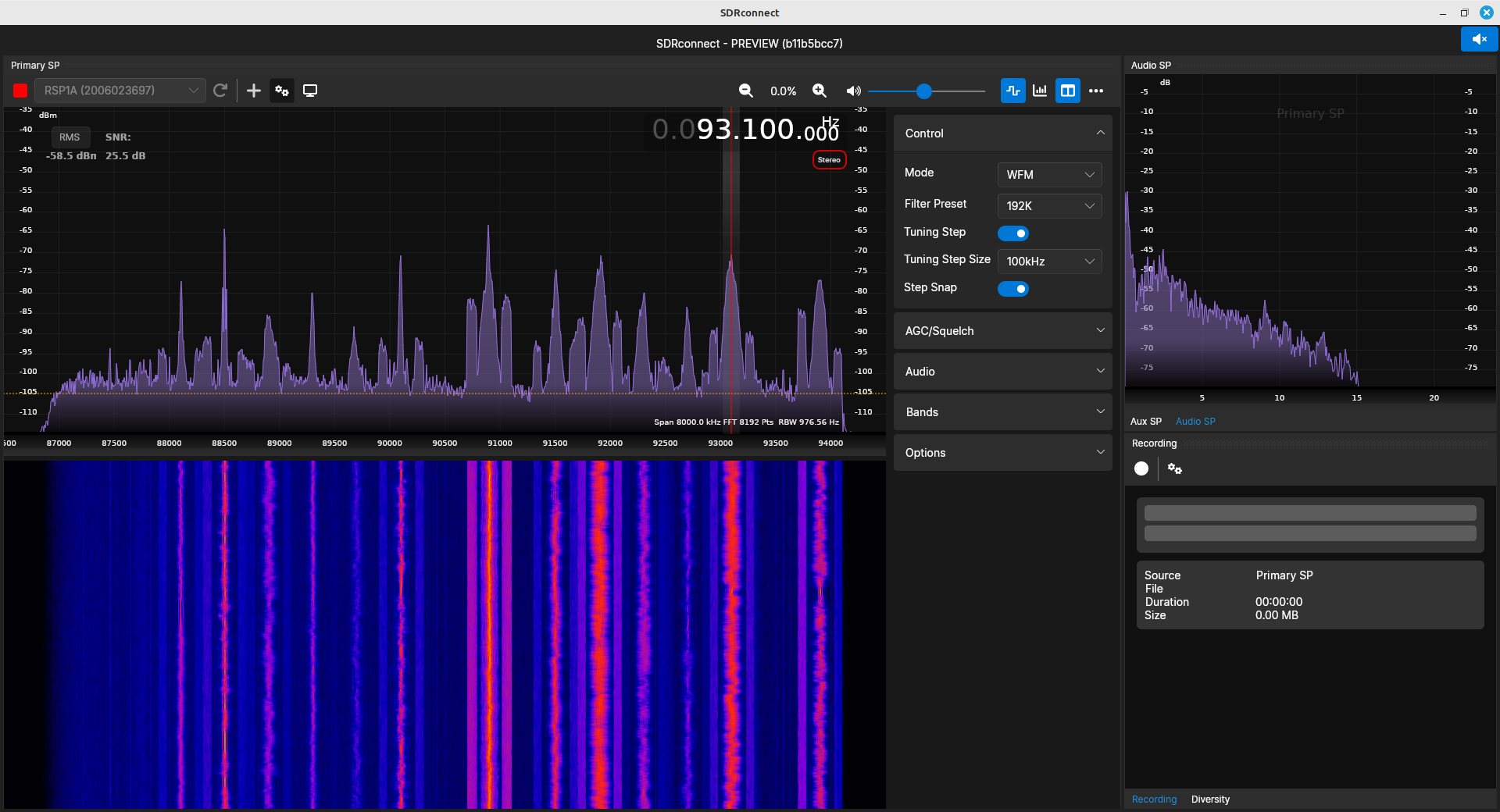
- An "auxiliary" RF spectral trace and spectrogram: These are in the upper, righthand corner of the main SDRconnect window. These are zoomed-in displays that allow the user to center on narrowband signals. The span of these displays is determined by the chosen demodulator. This is especially useful when the sample rate is relatively high, such as 1 MHz or higher. Narrowband signals, such as aircraft communications and various amateur radio communications, would only be a small fraction of the full spectrum. This display makes it easier to tune in the signals properly. By clicking near the signal, the zoomed in spectra can be used to center the signal properly.
- An audio (demodulated) spectral trace: This shows the spectrum of any modulated signals extracted from the carrier. IMO, this would be better if it was the full spectrum of the demodulated signal, not just the audio frequencies.
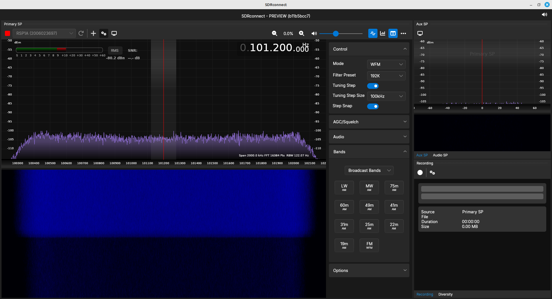
The span is set by the sample rate. As stated before, SDRconnect provides either a "low IF" or "zero IF" depending on the sample rate. At 2 MHz and below, it's using the "low IF", meaning there will be no LO feedthrough at the center of the spectrum. SDRconnect uses "zero IF" for sample rates of 5 MHz and above. This means that, with these sample rates, you'll see spike at the center of the spectrum for these higher sample rates.
SDRconnect also lists a resolution bandwidth (RBW) in the lower, righthand corner of the spectral trace. Let me just get this out of the way now. It's wrong. What they're listing as the RBW is actually the binwidth, meaning the separation between the spectrum samples. Don't believe me? Take a look at the spectra above. It lists a span of "5000 kHz" (5 MHz) and the FFT of 32768 points (215). Dividing 5 MHz / 32768 = 152.59. That's what they list as the RBW. Except the RBW must also take into account the windowing used on the data before it's run through the FFT algorithm. SDRconnect lists the default window as "Sin3". I was not able to find that particular window listed in any of the normal references, but I was able to find the equation for it. I was able to calculate the NENBW for it, as well as for the "Sin5" listed under the "Display Settings" window. Given these values, the actual RBW with a "Sin3" window for the display above is 152.59*1.7349 = 265 Hz.
Below is a table listing the NENBWs for the various windows available in SDRconnect. To calculate the actual RBW, multiply the desired value (based on the chosen window) with the binwidth. Note that "Nuttall", "FlatTop", and "Blackman" are not specific windows; they're actually families of windows. I've made guesses as to the specific one within each family that SDRplay selected.
| Window | NENBW (bins) | PSLL (dB) |
|---|---|---|
| Sin3 | 1.7349 | -53 |
| Sin5 | 2.1347 | -69 |
| Nuttall | 2.0212 | -93 |
| FlatTop | 3.7702 | -76 |
| Blackman | 1.7628 | -58 |
The windowing affects three primary parameters of spectra. These are:
- Resolution bandwidth
- Dynamic range
- Amplitude accuracy
At first, I thought the difference between the windows would make a truly noticeable difference, especially between the "Sin3" (PSLL = -39 dB) and "Nuttall" (PSLL = -93 dB) windows. However, when looking at several different spectra (FM broadcast band, aircraft comms band, NOAA National Weather Radio, several of the cellular bands), I could not see a difference.
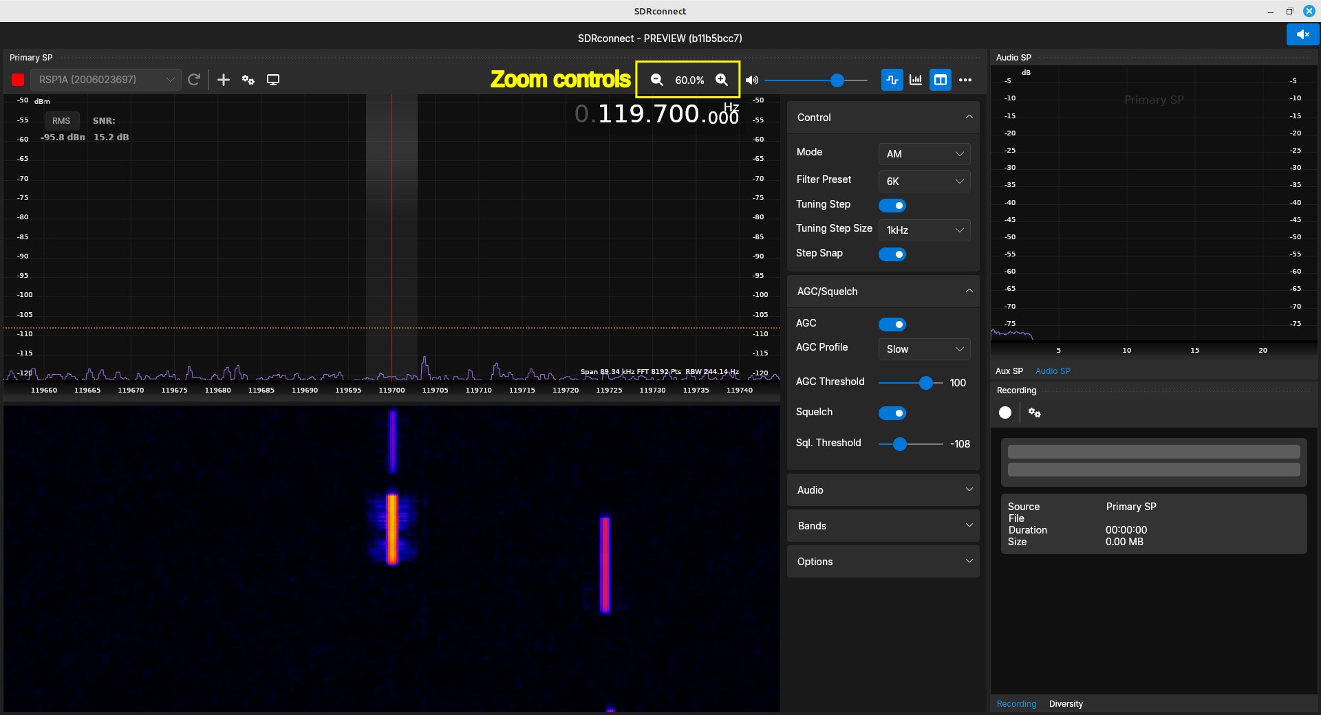
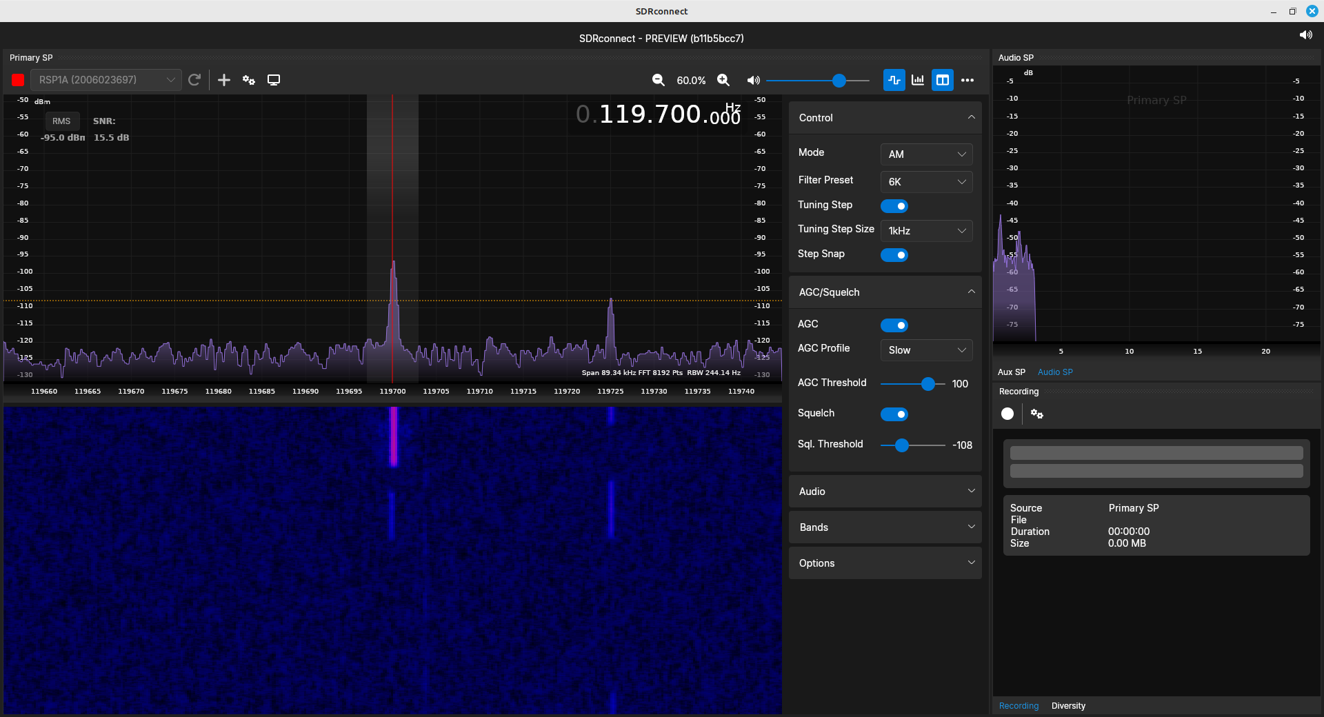
Adjusting the Spectral Displays
As stated, the span of the RF spectral trace and spectrogram are set by the sample rate. SDRconnect provides a method to zoom in and out of these displays.
Demodulators
SDRconnect's primary purpose is the demodulation of analog signals. It has almost every type of analog demodulator possible. This includes FM and most of the AM types possible (DSB, SSB with both LSB and USB, and CW.) One of the key points of this software that you need to understand is that the frequency listed in the primary spectral display is where the demodulator is tuned. The demodulation selected will also set the available demodulator bandwidths. These various settings (demodulator, bandwidth), as well as the step size for tuning, are all available under the "Control" section.
Demodulation requires three things. In order, these are:
- Set the frequency: The demodulator requires setting the center frequency correctly. This is because of the next step, which is...
- Set the bandwidth: A basic requirement for demodulation is ensuring that you have all of the desired signal, and none of anything past that. All of the noise and interfering signals outside of the desired signal must be eliminated. Setting the bandwidth does this.
- Set the demodulator: This determines how the information on the carrier will be extracted. The available possibilities are:
- AM: This is (probably) a noncoherent AM demodulator. This means it will demodulate any full carrier signal. It doesn't matter if the signal is double sideband (DSB) or single sideband (LSB, USB). The only type of full carrier signal this would not demodulate would be an independent sideband (ISB) signal.
- LSB: This will demodulate a lower sideband (LSB) AM signal, assuming it is suppressed carrier.
- USB: This will demodulate an upper sideband (USB) AM signal, again assuming it is suppressed carrier.
- NFM: This is narrowband FM. It doesn't effect the demodulator; it only affects the bandwidth. This demodulator provides bandwidths up to 25 kHz.
- WFM: This is a wideband FM. The only difference between this demodulator and the NFM demodulator is the available bandwidths. WFM provides bandwidths up to roughly 156 kHz.
- CW: Called "continuous wave", this is really just a very narrow bandwidth AM demodulator. This is primarily designed for Morse code using on-off keying (OOK). The preset bandwidths are up to 750 Hz, but its possible to adjust this bandwidth up to 13.5 kHz.
- SAM: This is synchronous AM. This refers to a synchronous demodulation of the AM signal. AM demodulation can be either noncoherent or coherent. "Synchronous AM" refers to coherent demodulation.
Setting the Bandwidth
So far as I can tell, SDRconnect does not have a way to set the bandwidth to a specific value using the keyboard. The only ways to set the bandwidth are by setting the demodulator (which sets the values to a certain range), using the "Filter Preset" values under the "Control" section, or using the cursor and mouse to click-and-drag the bandwidth on the RF or auxiliary spectral traces.
Of interest is that the available demodulator bandwidth can change based on the sample rate. For example, at a sample rate of 5 MHz, the maximum demodulator bandwidth, using the WFM setting, is 156 kHz. That increases to 250 kHz with a 8 MHz sample rate. But then it shifts back to 156 kHz at 10 MHz. This could just be a glitch in the software. Regardless, it's something of which to be aware.
Other Settings
While it's not typically part of the process, in this case, setting the sample rate also affects the demodulator. With a higher sample rate, the dynamic range is reduced. This can be seen in the spectra of the FM broadcast band with the different sample rates above. The signal at 90.9 MHz, when demodulated, is fairly clean at the 8 MHz sample rate (12 bits / sample), while at 10 MHz sample rate (8 bits / sample), the signal is fairly noisy.
| Audio from FM broadcast signal demodulated using SDRconnect at 8 MHz sample rate. Note that it is fairly clean. |
| Audio from FM broadcast signal demodulated using SDRconnect at 10 MHz sample rate. Note how noisy it is. |
Demodulated Processing
A modulated signal might require more processing than would a straight audio signal. Audio is straightforward. Demodulate the signal, filter the output, adjust the sample rate (set it to one your audio card can handle), maybe adjust the volume, and it comes out of your speakers. But what if the signal requires more than that? FM broadcast signals are a classic example. They're a composite signal. They have more than just audio. Stereo FM signals have two audio signals that, when combined (properly), gives you separate left and right channels with nice spatial effect. They may also have a RBDS signal. That requires even more processing. Other types of processing could be for ADS-B, or a trunked radio system.
SDRconnect is primarily designed for simple audio. The only, other processing type that it can provide (so far as I've found) is stereo FM broadcast. It will provide a stereo output.

There's also different displays that might be available, such as a demodulated time-domain or frequency-domain (spectral) display. SDRconnect only provides a basic, low frequency (less than 24 kHz) spectral display.
Recording
SDR software can record signals in one of two ways. The first is in its modulated form. This is typically done as an IQ signal. Such a signal can be processed later to extract whatever information is in the signal. SDRconnect does not provide this type of recording capability.
The other way signals can be recorded is in their demodulated form. This type of recording will depend on the type of information modulated onto the carrier. Audio signals can be recorded typically as .WAV format. This is the only recording type that SDRconnect does. It will record the demodulated audio from signals as a .WAV file.
Overall Thoughts
As I said at the beginning, SDRconnect is a major improvement over SDRuno. While it still has plenty of glitches (won't really run on my Windows 11 system, still has various issues on Linux), if SDRplay manages to get those resolved, it will be a great program for operating an amateur radio receiver. I've used it and my RSP1A SDR to listen to AM broadcast, citizen's band (CB), FM broadcast, aircraft communications, 2 meter amateur, and NOAA NWR signals. Considering I'm using a simple discone antenna in my attic, it has still been excellent for all of them.