
Random Quote Board
Demodulating Radio Broadcast Data System (RBDS) with Gnu Radio
20 November 2020 marked the 100th anniversary of the first commercial radio broadcast of KDKA in Pittsburgh. That station used amplitude modulation (AM), specifically double sideband, full carrier AM.
The Federal Communications Commission (FCC) issued the first grant for a FM station (W2XMN in Alpine, NJ) to Edwin Armstrong in 1936, and a license in 1938. More stations followed. In 1945, the FCC stated that,
The Commission may grant experimental authority to an FM station for the multiplex transmission of facsimile or other signals and aural broadcast programs...
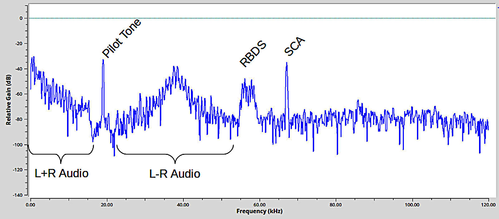
The idea was this. FM broadcast stations were primarily setup for audio broadcast. The FCC was saying, "You can also transmit other information on an experimental basis, so long as it does not interfere with your primary audio broadcast." That "other information" would be modulated onto low frequency (tens of kHz) carrier waves, added together with the main audio, then modulated onto the RF carrier. This would create a composite signal combining several signals together.
Thus began the idea of "subcarriers", or secondary channels of information transmitted on FM broadcast stations. Subcarriers became a way of multiplexing different information onto the same carrier.
The Federal Register of March 25th, 1955, stated that WTOP, an FM broadcast station in Washington, DC, had already tested this idea of "sub-channels" on their own station in the summer of 1953. Those tests showed that facsimile, teletype and voice communications could also be "impressed" (modulated) onto the main carrier without affecting the main carrier operation. This was their conclusion:
It is our conclusion, based on these reports and our knowledge of the multiplex facsimile operation, that multiplex operation by FM broadcast stations is feasible. Feasibility depends on satisfaction of two criteria: that the sub-channel operation not interfere with the main channel signal, and that the sub-channel signal be of usable quality.
The Radio Broadcasting Data System (RBDS)
Fast forward to 1984. European groups developed the Radio Data Service (RDS). It was a digital subcarrier designed to pass certain pieces of information. This included program type (jazz, rock, etc), program identification (identify the station, such as by call letters), and program service information (originally just static station information, but now generally station name, song artist, and song title).
The US adopted a similar system which it called "Radio Broadcasting Data System (RBDS)" in 1992. That system is now installed on many, if not most, FM broadcast stations here in the US.
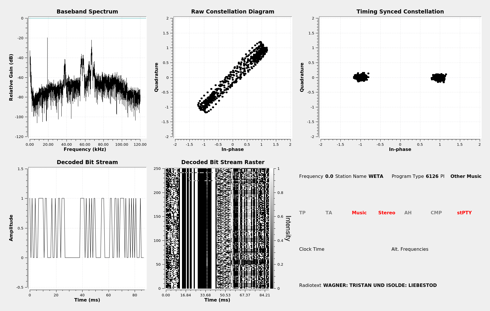
Many, if not most, stations nowadays will carry several such "sub-channels" of information. Below is but one example. This one is from WETA, an FM broadcast station also in Washington, DC.
Before we get too far into the weeds, let's make certain we all understand some basics of digital signals. First, there is the encoding, or how the digital bit stream is put together. This refers to how the bit stream is created based on the information it contains (source coding) as well as how it is further altered based on randomization, channel coding (error correction, synchronization, framing), interleaving, line coding, and pulse shaping. The second aspect is the modulation, meaning how the signal is impressed onto the carrier in order to convey the information from point A to point B.
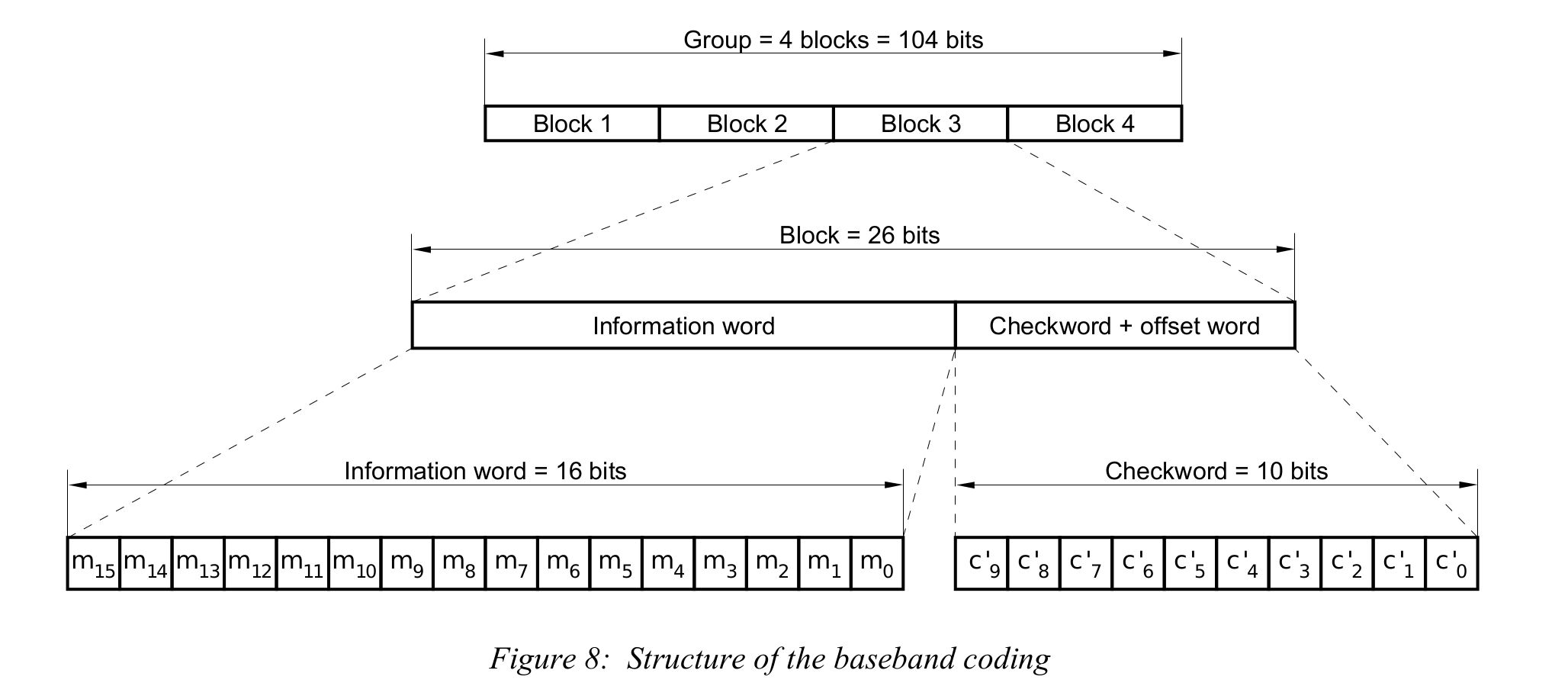
The RBDS starts as four groups, with a 16 bit block in each group. Those four groups of 16 bits represent a lot of information. RBDS provides information on the type of station (classical, rock, religion, etc), the name of the current song, the artist, the station identifier, and even the current date and time.
A 10 bit checkword is added to each block to create four groups of 26 bit blocks each. There's a fair amount of processing that goes along with the creation of these checkwords. The result is a fair amount of redundancy in the signal, such that the efficiency of the signal has dropped to just over 61%. The upside is that the information can be recovered even with a relatively low signal-to-noise ratio (SNR).
The bit stream is then differentially encoded. At this point, it has a bit rate of 57000/48 = 1187.5 Hz. The bit stream is Manchester encoded. Manchester encoding is a dipolar line coding, which means it has no DC component. It does, however, double the bit rate (2375 Hz). It's pulsed shaped (filtered). (NOTE: In one of those "Well, actually..." moments, the original design has the pulse shaping and Manchester encoding occurring at the same time.) The modulation is two-level amplitude shift keyed (2ASK) suppressed carrier. This is identical to a 2-level phase shift keyed signal. The carrier center frequency is 57 kHz, or three times the pilot tone frequency of 19 kHz.
Demodulating RBDS
Demodulating and decoding a RBDS signal is the reverse of the above process.
NOTE: For this demonstration, I'm using Gnu Radio Companion 3.8 running on Linux Mint 20.2. I've also installed "gr-rds" from "Software Manager". I was able to make this work on Windows 3.7, but I had to disable all of the QT GUI displays and set the "Options" block to "WX GUI" for the RDS decoder. In other words, with Windows 10 and GRC 3.7, I can either have the various time and frequency displays or I can have the RDS display.
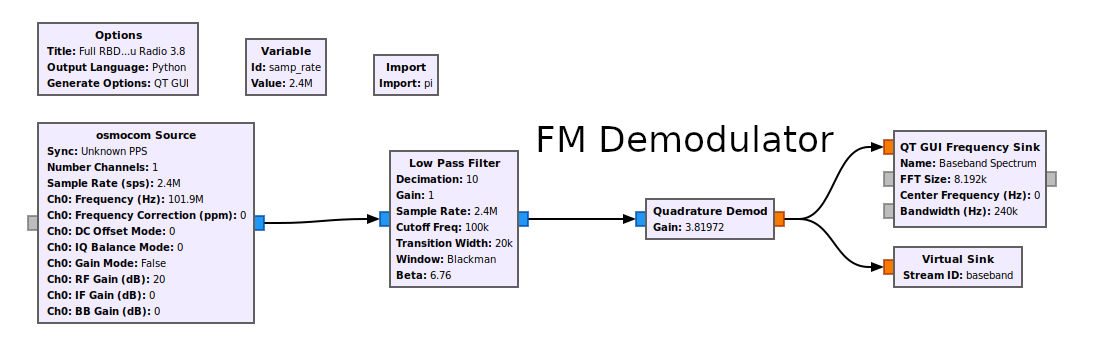
I'm just going to provide the whole Gnu Radio graph up front, then I'll walk through it a section at a time. I've made liberal use of virtual sinks and sources. That keeps down the number of lines, and makes the graph less scary. Each source / sink marks a new section. There are five sections in total. Let's go through them one at a time.
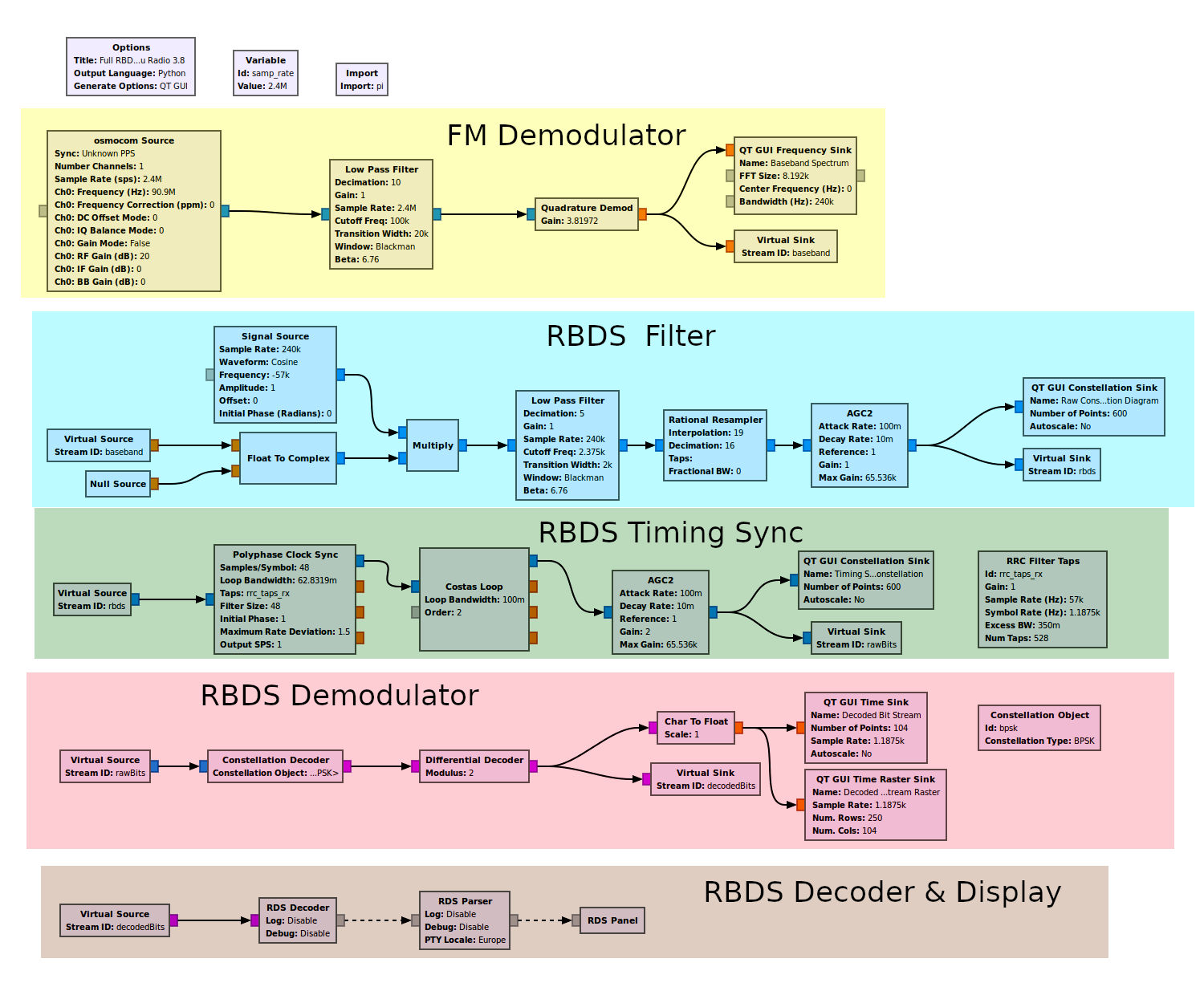
FM Demodulator
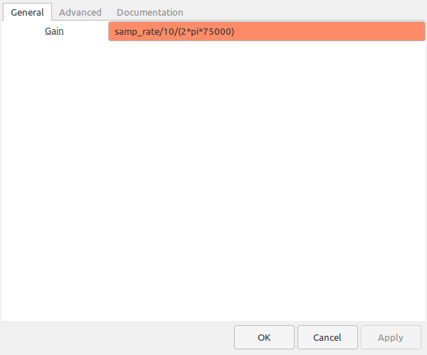
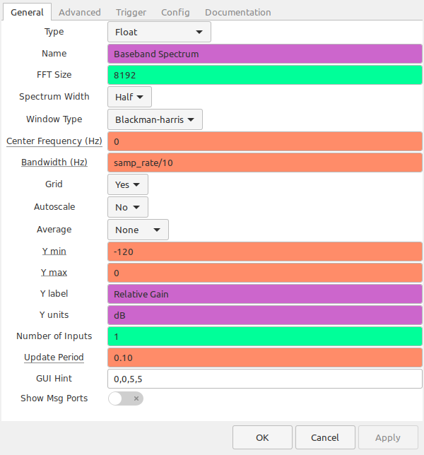
Before we can demodulate the RBDS signal, we first need a RBDS signal. This requires finding a FM broadcast signal containing a RBDS signal. Most FM broadcast stations I've seen have such signals. I've outlined several, possible frequency demodulators that you can use to access the baseband of the FM station. For this post, I'm going to use a basic (and poorly named) "Quadrature Demod" block. This is a polar discriminator.
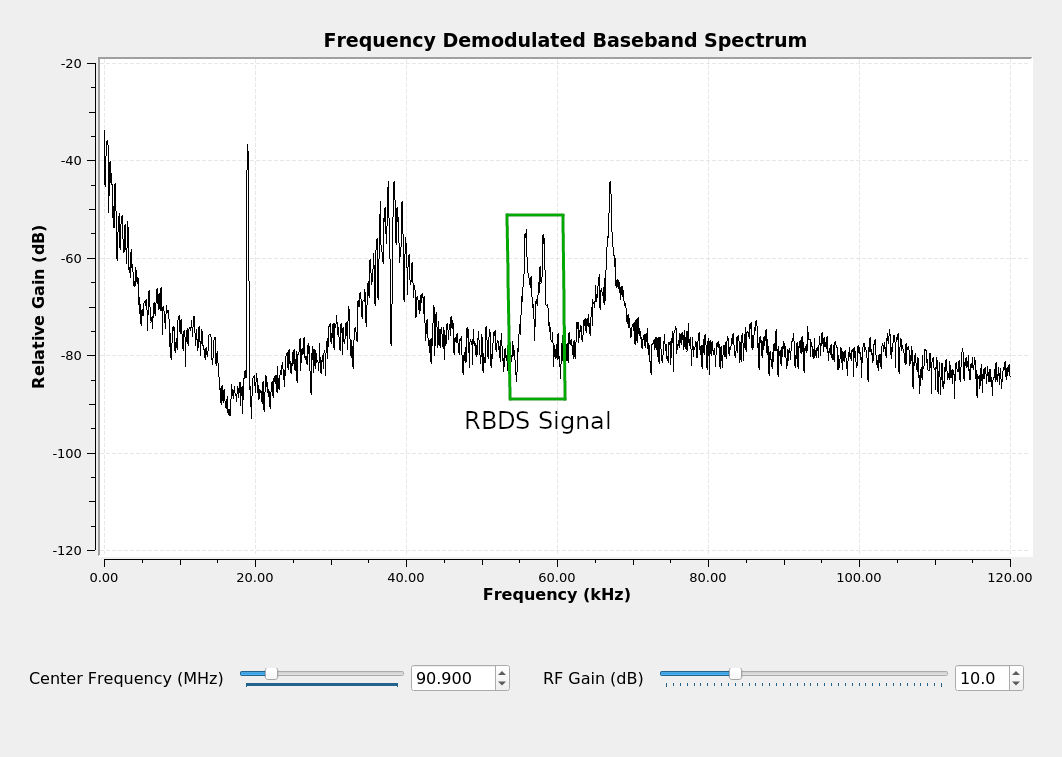

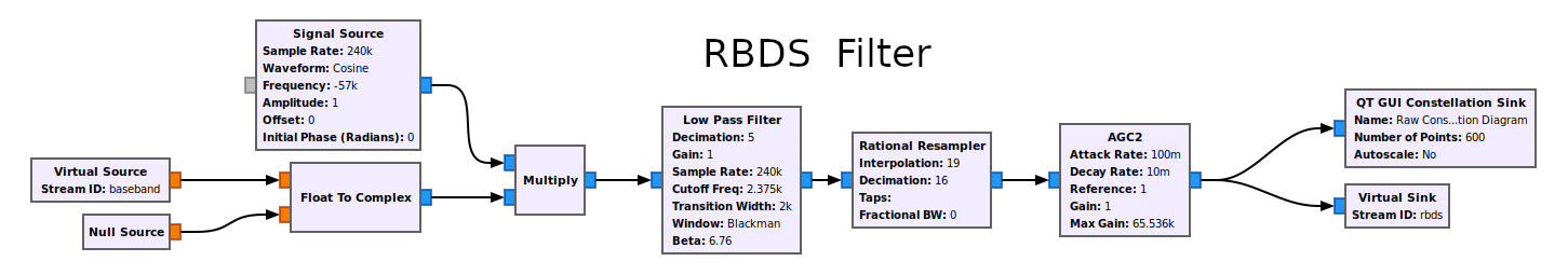
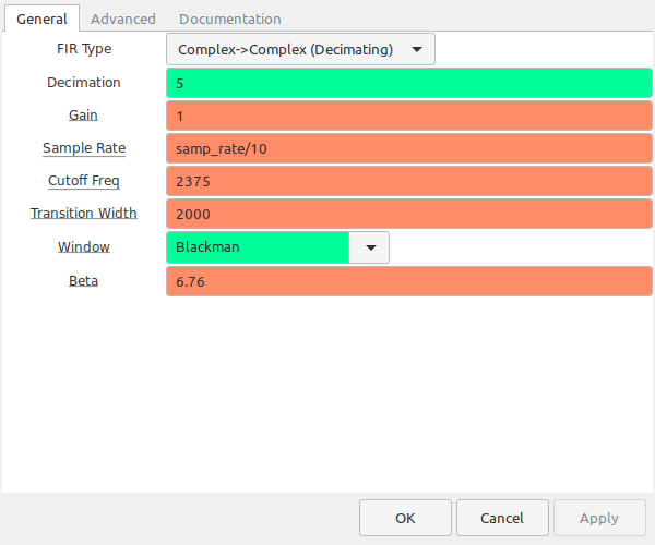
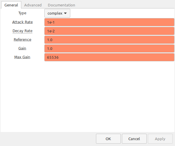
RBDS Filter
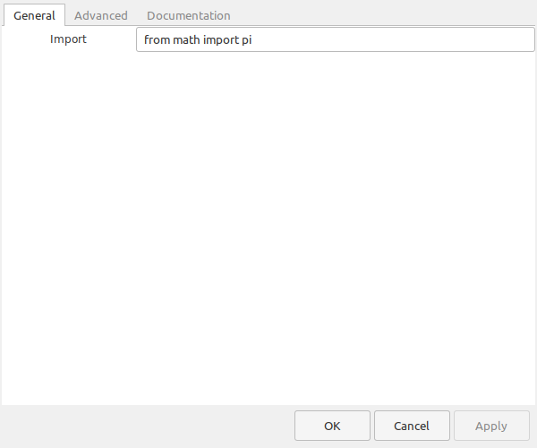
The next step is to isolate the RBDS signal from all of the other baseband signals. I'm going to use a complex frequency shift so that I don't have to filter the signal first. I'm going to shift the signal down to 0 Hz, then use a single lowpass filter to isolate it. Shifting the RBDS signal to 0 Hz will also prepare it for demodulation.


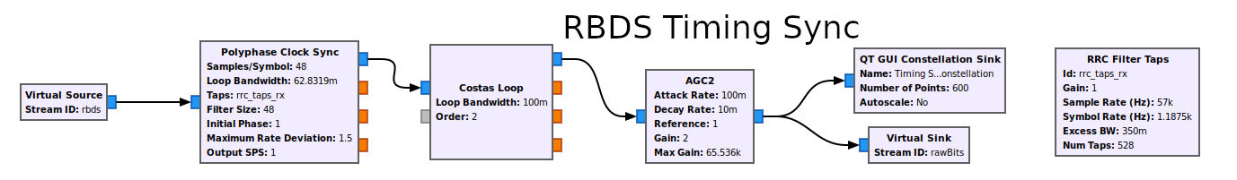
RBDS Timing Sync
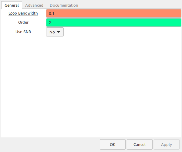
This section synchronizes the samples with the center of each bit. It performs a matched filtering using a root raised cosine (RRC) with an alpha value of 0.35, then performs the Manchester decoding. The Costas loop phase syncs the constellation. The output is a stable 2-point constellation. The nice thing about this circuit is that it does not rely on a 19 kHz pilot tone in order to properly lock to the RBDS signal. This is good because (a) not all stations have a 19 kHz pilot tone and (b) even those stations that do have such a pilot tone don't use it to sync with the RBDS signal. (NOTE: I discovered at least three stations here in the Washington, DC and Baltimore area that don't use the pilot tone to phase lock with the RBDS signal. That was an interesting discovery.)


The short video below shows how the circuit syncs its timing to several, different RBDS signals.
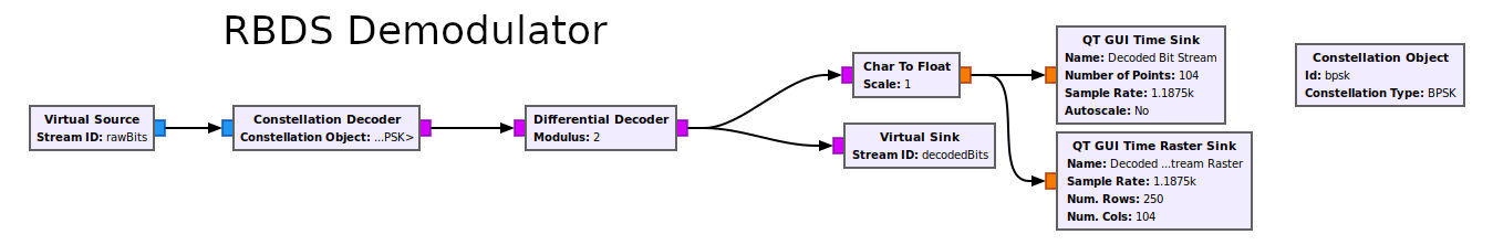
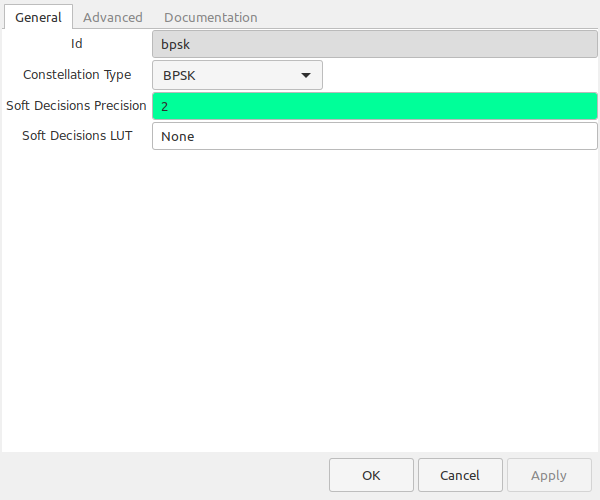
RBDS Demodulation
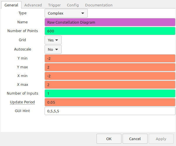
Okay, we have the RBDS signal isolated, and we're synchronized to the bit stream. At this point, you should have a constellation diagram that shows two clusters, one at -1 and another at +1, both on the real line. The next step is to actually demodulate the signal. To do so, I'm going to use the fact that a two-level amplitude shift keyed (ASK) signal with suppressed carrier is identical to a binary phase shift keyed (BPSK) signal. After that, it's the process of stripping off the differential encoding. Here's the interesting thing about the differential encoding. While I have a Costas loop above, it's not needed for this circuit. The differential encoding means that the bit stream doesn't care about the absolute value of each bit, but only the transition between bits. So long as we have clear transitions, the signal will decode properly.


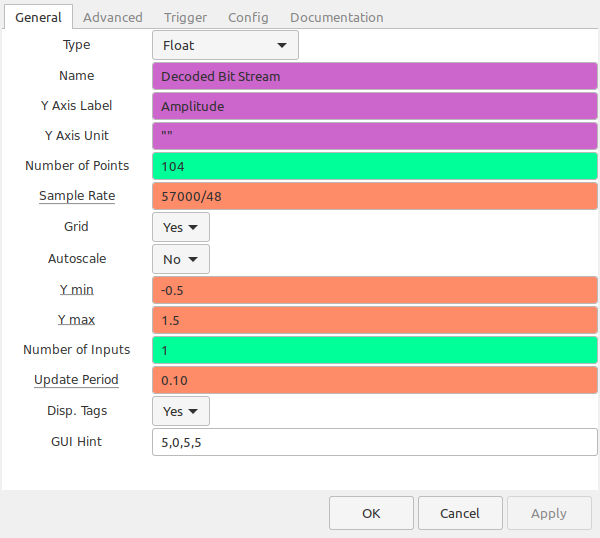

RBDS Decoder and Display
The last part is to actually decode the RBDS bit stream and display the actual information. For this, we need three, separate blocks in Gnu Radio. These are shown below.
These three blocks have no, real user settings. You're not adjusting a sample rate, or telling Gnu Radio how many samples per symbol, or setting the bit rate or bandwidth of the system in these blocks. Yet these three blocks are probably performing the vast majority of the processing in this entire graph. These blocks have to ensure that the bits were properly received using the checkword, which itself requires a fair amount of processing. Then it has to parse out what the bits mean which, again, means a bit of processing. The point is that the people who put together the "gr-rds" branch of Gnu Radio deserve a lot of praise for making this plug-in.

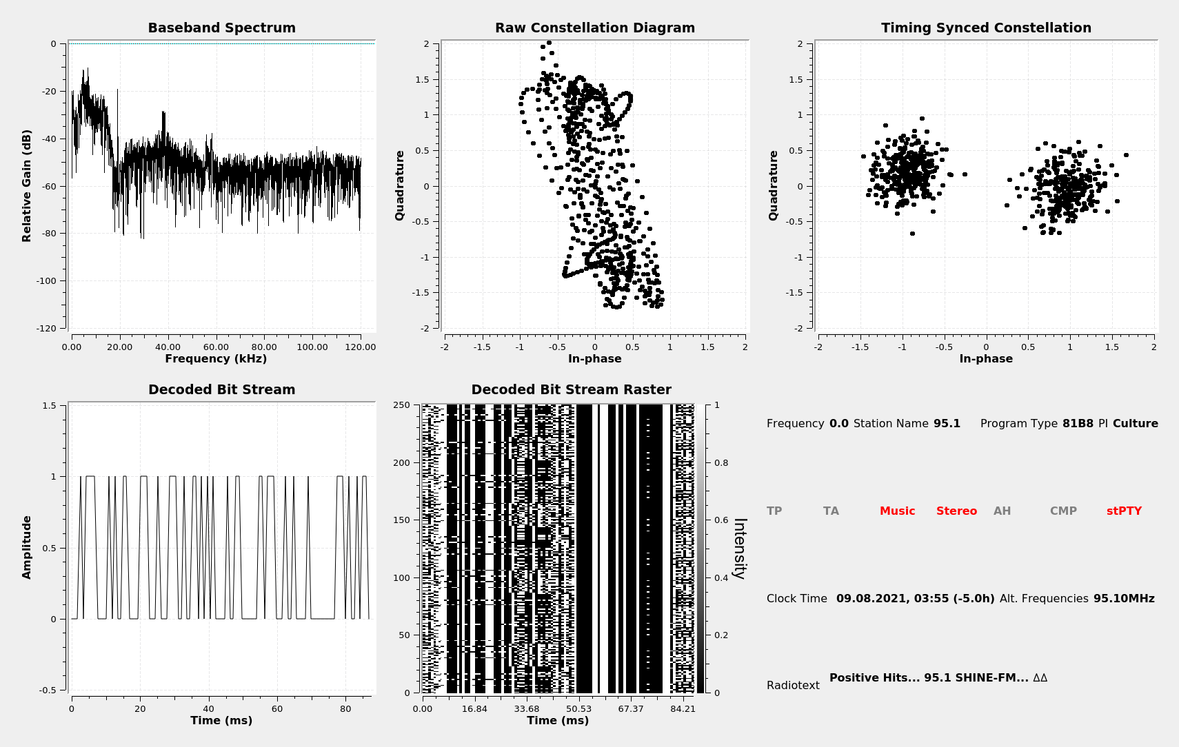
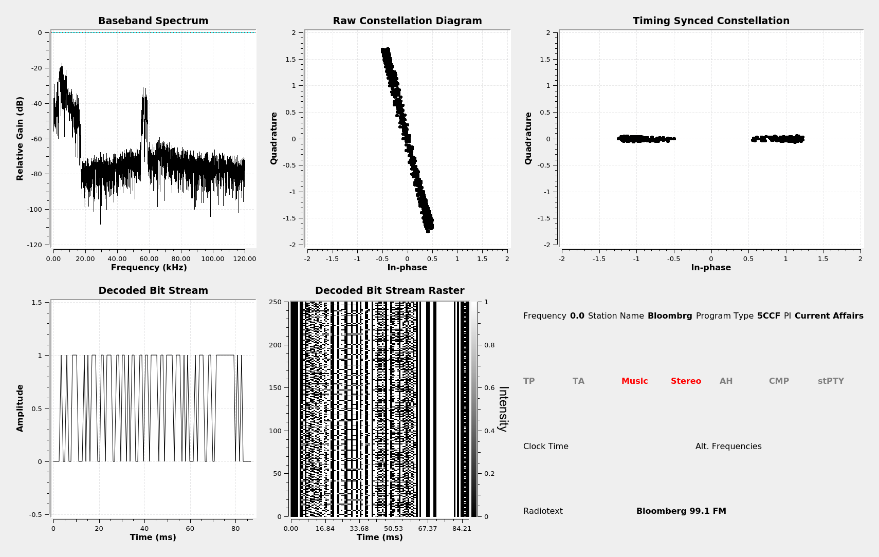
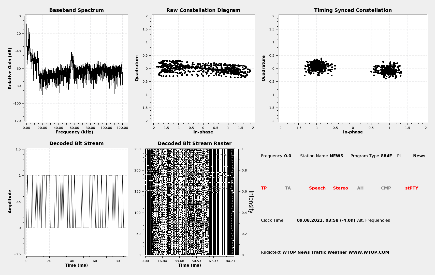
RBDS Display Examples
I chose four, different stations as demonstrations for my demodulating and decoding circuit. These are shown below.
Summary
This was another fun post to put together. Who am I kidding? They're all fun. If they weren't, I wouldn't be doing this. Regardless, I enjoyed putting this post together due to the combination of analog and digital techniques this type of signal combines. We'll see where it takes me for my next post.