Random Quote Board
Summary of Amplitude Demodulation with Gnu Radio
In my previous post on amplitude demodulation, I looked at several ways to amplitude demodulate a signal. They were all based on AM demodulators listed in a Rick Lyons post. With this post, I'm going to simply cover three demodulators that should cover just about any type of amplitude modulation.
Quick Review
An AM signal has two primary parameters. These are the presence or absence of a tone at the carrier frequency (carrier condition, i.e. "full carrier, "suppressed carrier", "reduced carrier") and the presence of either or both sidebands (sideband condition). For example, AM broadcast signals in the US (540 - 1700 kHz) are full-carrier, double-sideband (FC-DSB). This is also the case for aircraft communications in the band between 118 - 137 MHz. A different signal is the stereo signal in FM broadcast transmissions; it is a double sideband, suppressed carrier signal.
There are two basic ways to amplitude demodulate a signal. These are noncoherent and coherent.
- Noncoherent: this means the receiver does not need to phase lock with the carrier frequency. Only full carrier signals can be noncoherently demodulated. Noncoherent will work with any full carrier signal except for independent sideband. For that, we need to use coherent demodulation. But for all of the others (single sideband, double sideband, vestigial sideband), noncoherent will work.
- Coherent: this means that we have to phase lock to the signal, or get close enough that the difference does not matter. If you're wondering, "When would it not matter?", think audio signal. You can be off by a few Hz for an audio signal and still have intelligible audio. Any type of suppressed carrier requires coherent demodulation.. Coherent demodulation can use a Costas loop (for double sideband) or carrier injection, typically using a beat frequency osccilator (BFO), for single sideband.
To summarize how we can demodulate the different types of AM signals:
- Full carrier: With the exception of independent sideband, we can use the complex magnitude detector on any signal using a full carrier.
- Double sideband, suppressed carrier: We can use the Costas loop for this type of signal.
- Single sideband, suppressed carrier: Use a digital "beat frequency oscillator (BFO)", then simply tune as close as possible to the center frequency. Use the BFO to make the signal look or sound as good as possible. If there's some type of pilot on the demodulated output, you can use that to tune the frequency. This would be a signal-specific thing, and not something that would be universal.
Complex Magnitude AM Demodulation
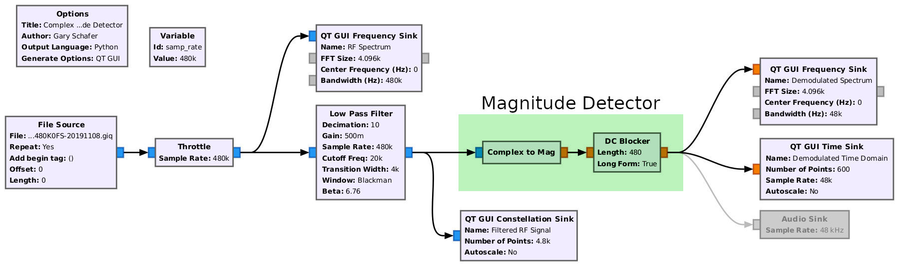
Let's start with perhaps the most basic noncoherent demodulator from the perspective of a complex signal, the complex magnitude demodulator. NOTE: There may actually be an official name with IEEE or some other august organization for this type of demodulator. If so, they're being pretty quiet about it. Until someone gives me such an official name, I'm going to call it the "complex magnitude detector". NOTE #2: I used this block in a GRC flowgraph in my previous post when discussing the asynchronous complex envelope detector.
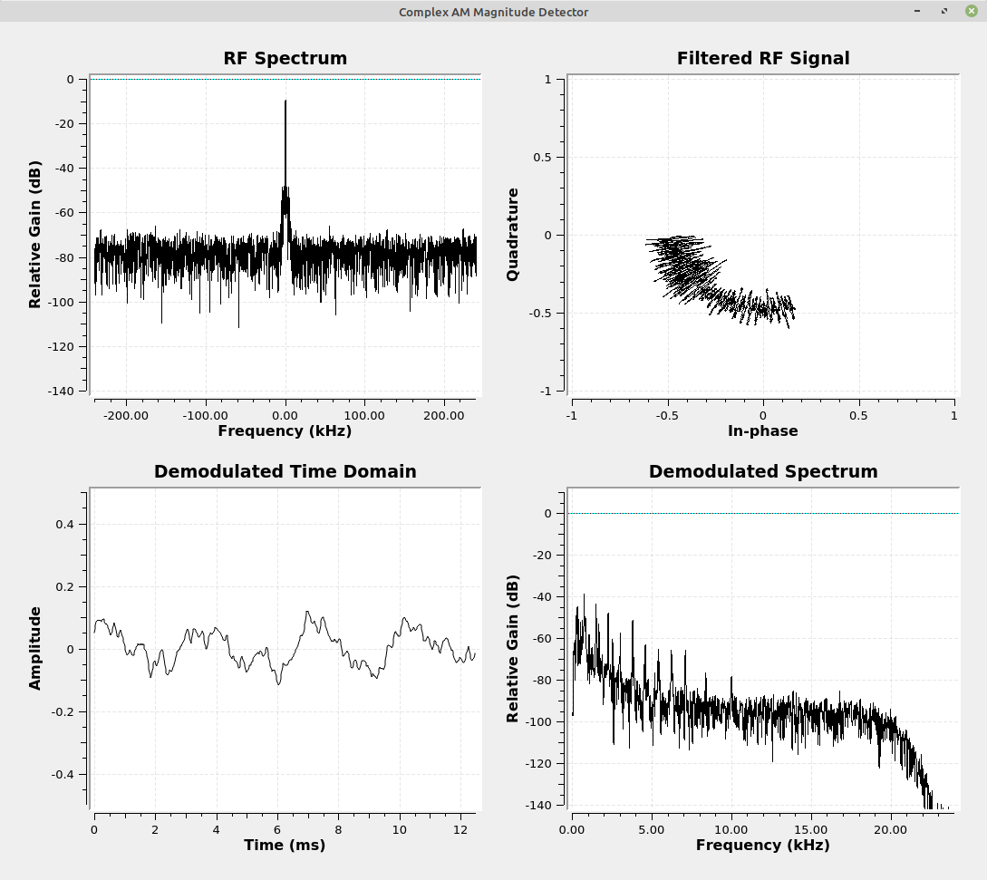
The idea is this: When we look at the polar plot of the complex signal, we see that the baseband signal varies the magnitude of the signal. Further, due to the fact that the signal is full carrier, which means an offset from the center of the polar plot, we don't have to worry about the magnitude passing through the center. That would mean having to determine if the signal is negative or positive once it passes through the center.
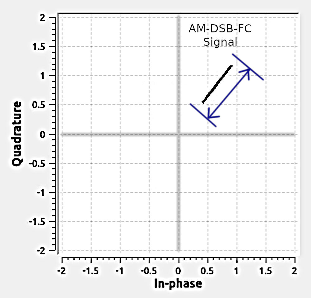
We can use the "Complex to Mag" block to calculate the magnitude of the signal over time. The really good part? It doesn't matter if we're not phase or frequency locked. The constellation can be spinning (meaning we're off from the center frequency of the actual signal) and this detector will still work just fine. We only care about the magnitude (distance from the center of the constellation); frequency and phase are irrelevant. Hence, noncoherent.
Second, the output will not have any harmonics. This is unlike the other noncoherent methods. The half-wave rectified, full-wave rectified and squaring operations all create higher order harmonics. The "Complex to Mag" block does not. This should mean that you do not need a filter at the output of this block. (NOTE: Lyons stated as such in his post. He recommended that you check to see if a filter is needed based on your particular circumstances. I consider this great advice.) We'll also need to add a "DC Blocker" to get rid of the DC bias.
Coherent Demodulation
There are two methods for coherent demodulation. These are:
- Costas loop: This method uses a Costas loop to frequency and phase lock to the carrier. (NOTE: Again, I point out that the term "suppressed carrier" is a misnomer. The carrier is, and always will be, still there. Otherwise, there would be nothing to modulate.) We can use the Costa loop for any double sideband
- Carrier injection: This method multiplies the signal with a sinusoid at the carrier frequency. The problem is frequency and phase locking between the injected sinusoid and the modulated signal. We can't do that with single sideband, suppressed carrier signals. In this case, we have to multiply the signal by a sinusoid. This is the "carrier injection". In old single sideband systems, this was called a "beat frequency oscillator" or "BFO". We can make a similar circuit in GRC using a "Signal Source" block combined with a "Range" and "Multiply" block.
Coherent Demodulation with the Costas Loops
Here's where I start with an apology. In my last post, I stated:
Unfortunately, the Costas loop in Gnu Radio is not the type that can be used on analog signals. It's designed for digital signals.
That's wrong. It turned out that I just didn't understand how to use the Costas loop block in Gnu Radio properly. Now that that has been corrected, allow me to show you how to use it properly to demodulate a suppressed carrier AM signal.
Here's a basic block diagram of a Costas loop, courtesy of the Electrical and Computer Engineering Department at the California State University, Fresno.
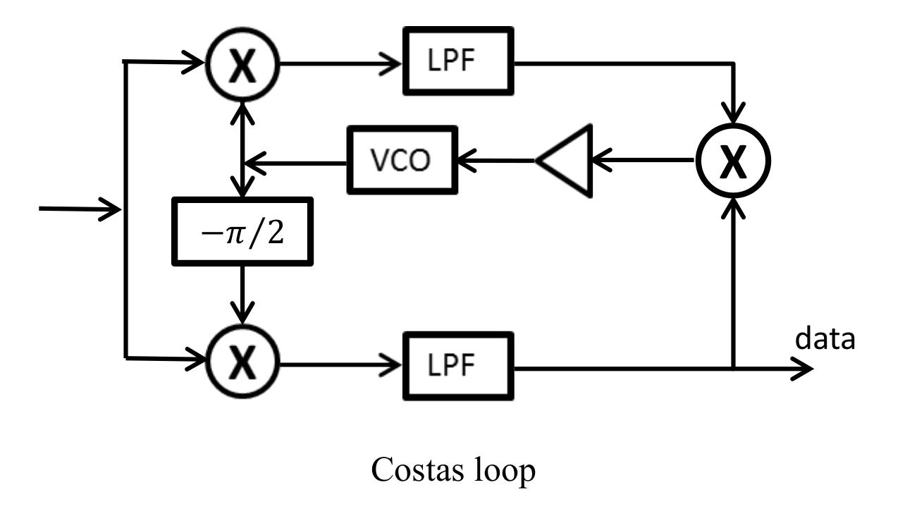
In GRC, the Costas loop will replace the complex magnitude demodulator. The output of the loop is still complex, so it needs to be converted to a real signal. The Costas loop will frequency and phase sync to the input signal. It will not guarantee that the output phase will be directly in phase with the input phase; it will simply ensure that the output constellation will be locked, not spinning. The "Complex to Float" and "Add" blocks will ensure that the output does not depend on the particular phase the constellation stops at.
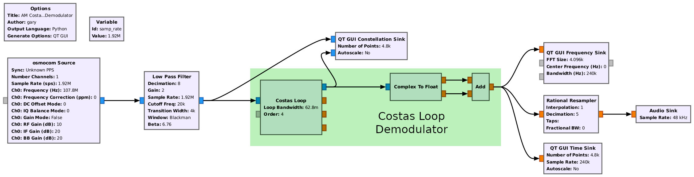
The constellation diagram on the right is a short video showing the constellation of the input signal (black) compared with the output (red).
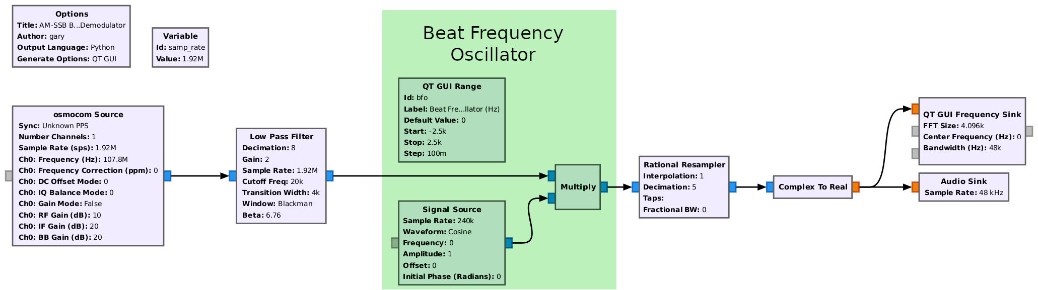
Carrier Injection (aka "Beat Frequency Oscillator")
The "beat frequency oscillator" or "BFO" is used to recover signals from either CW (continuous wave, typically used for Morse code transmissions) or single sideband (SSB) transmissions.
Think of a BFO as a frequency shifter. For CW signals, the BFO shifts the frequency to make the Morse code into a tone that the user can readily hear. For SSB, the BFO shifts the frequency for an audio signal such that it "sounds right".
In the days of analog circuits, the BFO would create a rather high frequency. The incoming signal would be mixed with the BFO. This would create an intermediate frequency (IF) at a relatively low frequency. It would also create a double sideband, full carrier signal. This signal would be demodulated using a basic AM noncoherent detector. The BFO frequency would be adjusted til the CW or SSB signal sounded "right".
This circuit is a little different. Because the incoming signal is complex and already at baseband, we don't need to demodulate it. The signal is already at the frequency we want. Or close to it. We just need to shift its frequency until it's "right". "Right", in this context, is in the ear of the beholder.