Random Quote Board
Quick Rather Deep Overview of SDRangel
I've used most of the popular SDR programs. This includes CubicSDR, SDR#, SDR++, GQRX, SDRuno, SDRConsole, HDSDR, and SDRangel. To me, they all provide the same basic information (center frequency display, spectral display). It's what they do after that that sets them apart. For example, SDR#, SDRangel, and SDRuno all provide a bunch of other processing, such as different types of signal demodulation and signal decoding.
The hard part? Trying to figure out how to get the blasted program to do what you need it to do. The only thing that is "intuitively obvious to the casual observer" about these programs is that no one from Apple's user interface crew showed up to help them design their interfaces.
Today, I'm going to start with a walk through SDRangel. I'd originally planned on making this a quick overview. It quickly expanded. It's now going to be a rather deep overview. I'm going to use both Gnu Radio and SDR hardware images to explain the general signal flow for SDRangel. I'm using SDRangel version 7.11.0 which I built from source in March 2023. I'm running it on Linux Mint 21.1 Cinnamon. The general flow should be the same for the same version regardless of OS.
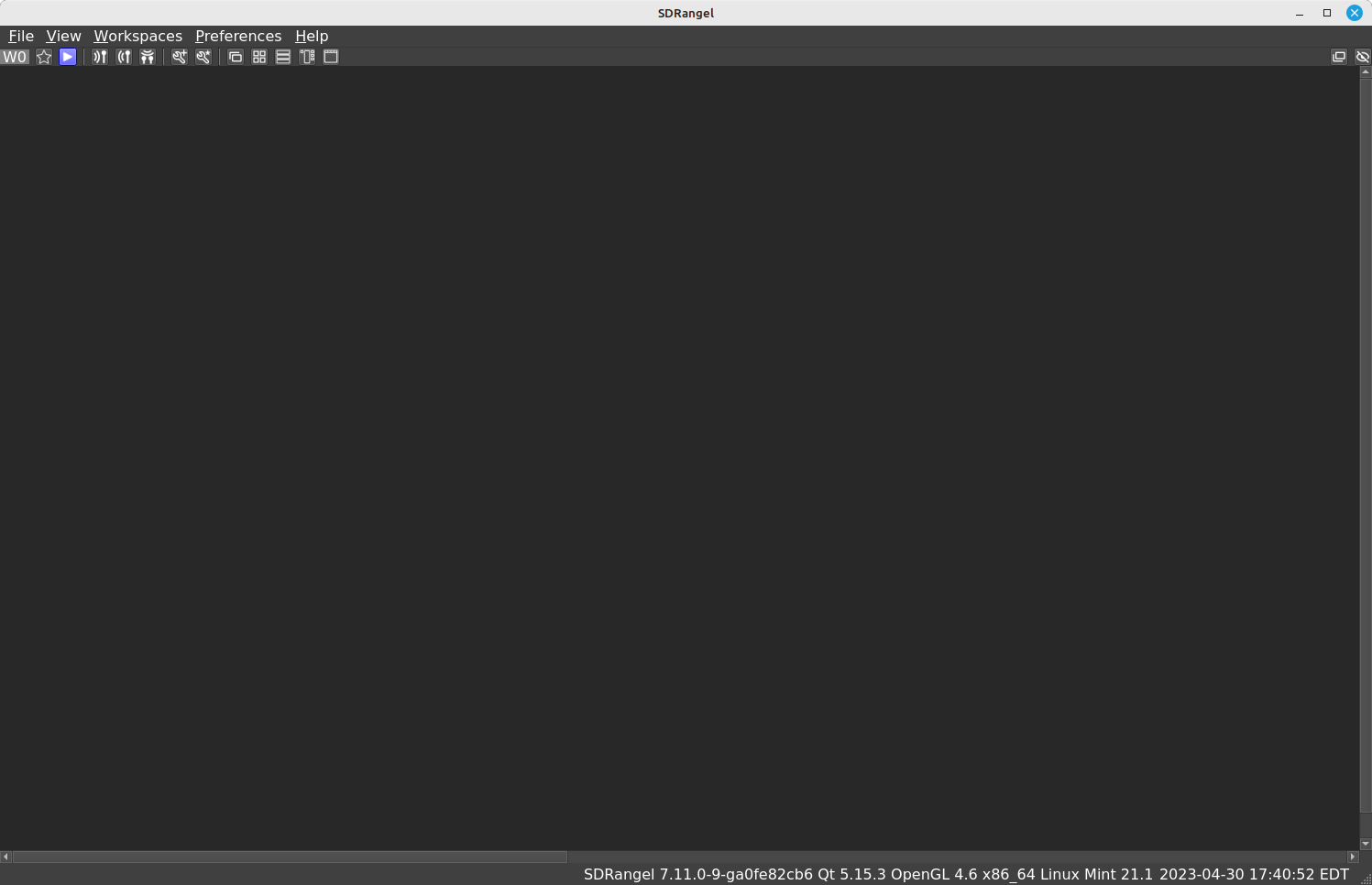
You're presented with a blank screen the very first time you open SDRangel.
Getting the Hardware Running
The first thing that is required in order for a SDR program, any SDR program, to work is to get samples off of the SDR hardware. This means ensuring that the drivers are working. Sorry, but I can't help you with that. The permutations of operating system and dependencies is too great.
After that, you need to have the SDR set to give you the right samples. "Right samples" means at the correct frequency with enough bandwidth and with the correct amplitude. This requires a few basic settings. These are:
- Input: For those systems that have multiple inputs and outputs (USRPs, LimeSDR), you need to ensure that you're connected to the RF input that will actually get you signals. For example, I have a Ettus Research B200mini. The B200mini has a "TRX" input / output, and a "RX2" input. When using this radio, I have to ensure that I've selected the correct input in order to get signals properly. (NOTE: With the B200mini specifically, it has very little isolation between the two inputs, so its possible to still receive signals on one of the inputs even when the other one is selected.)
- Center frequency: This sets the frequencies of the various oscillators so that the spectrum around the desired center frequency will be mixed down to the appropriate intermediate frequency (IF). That IF (most likely) is sent to the quadrature demodulator (convert real to complex) circuit.
- Sample rate: This sets the sample rate of the digitizer. It sets the available bandwidth coming off of the SDR. In general, available bandwidth is roughly the sample rate.
- Gain: Every SDR comes with a variable amplifier at the beginning of the RF front end. Some come with other, variable amplifiers further down the RF chain. SDRangel comes with the ability to adjust those amplifiers that are adjustable.
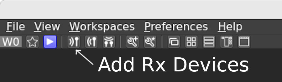
You have to add a window to control the SDR hardware. I'm going to add a RTL-SDR as my SDR hardware. I first ensured that the RTL-SDR was plugged into my computer. I clicked on the "Add Rx Device" icon, then selected the RTL-SDR from the dropdown menu.
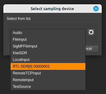
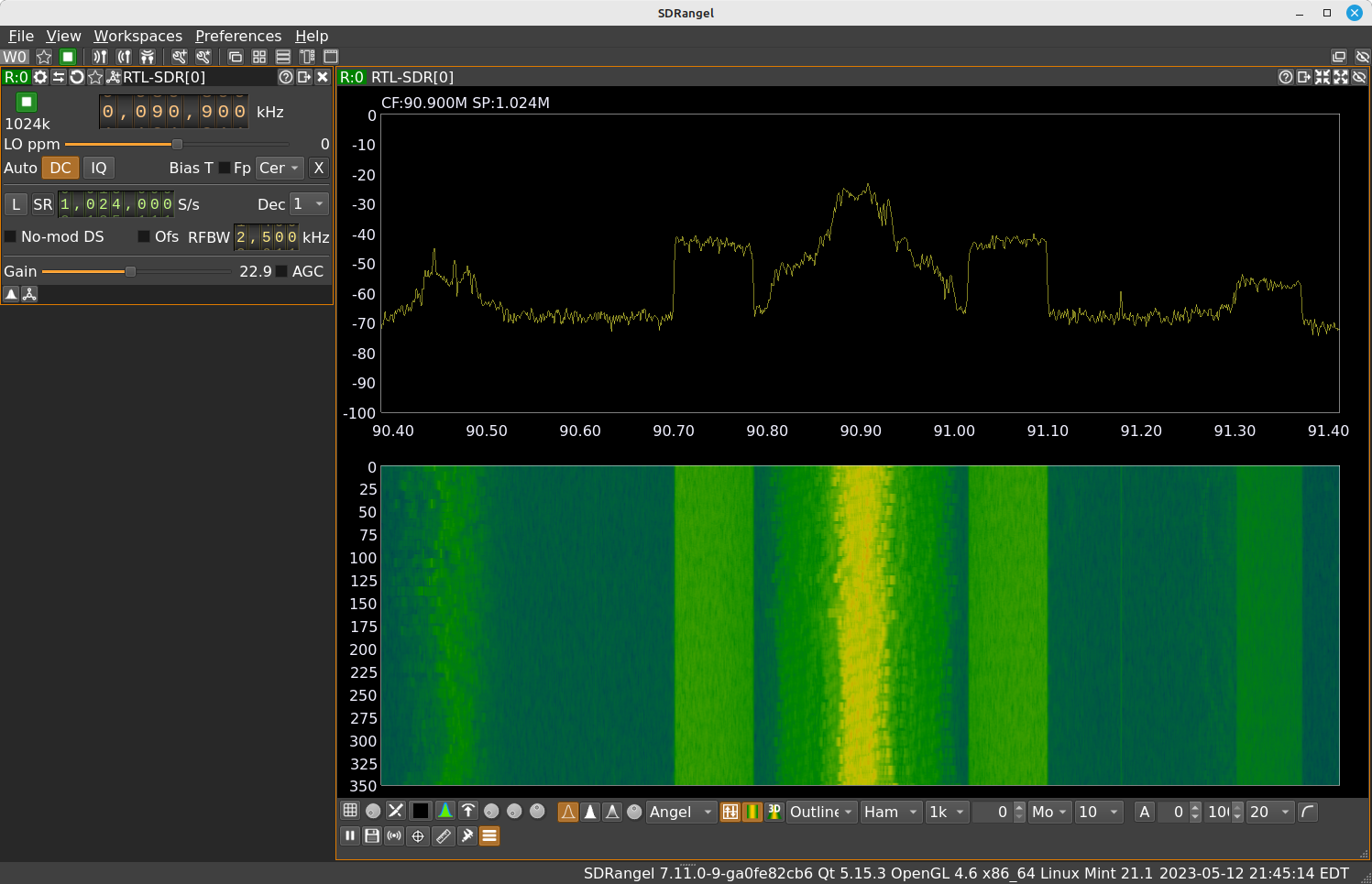
Once you select the desired receiver and press "OK", you're presented with two windows, as shown below.
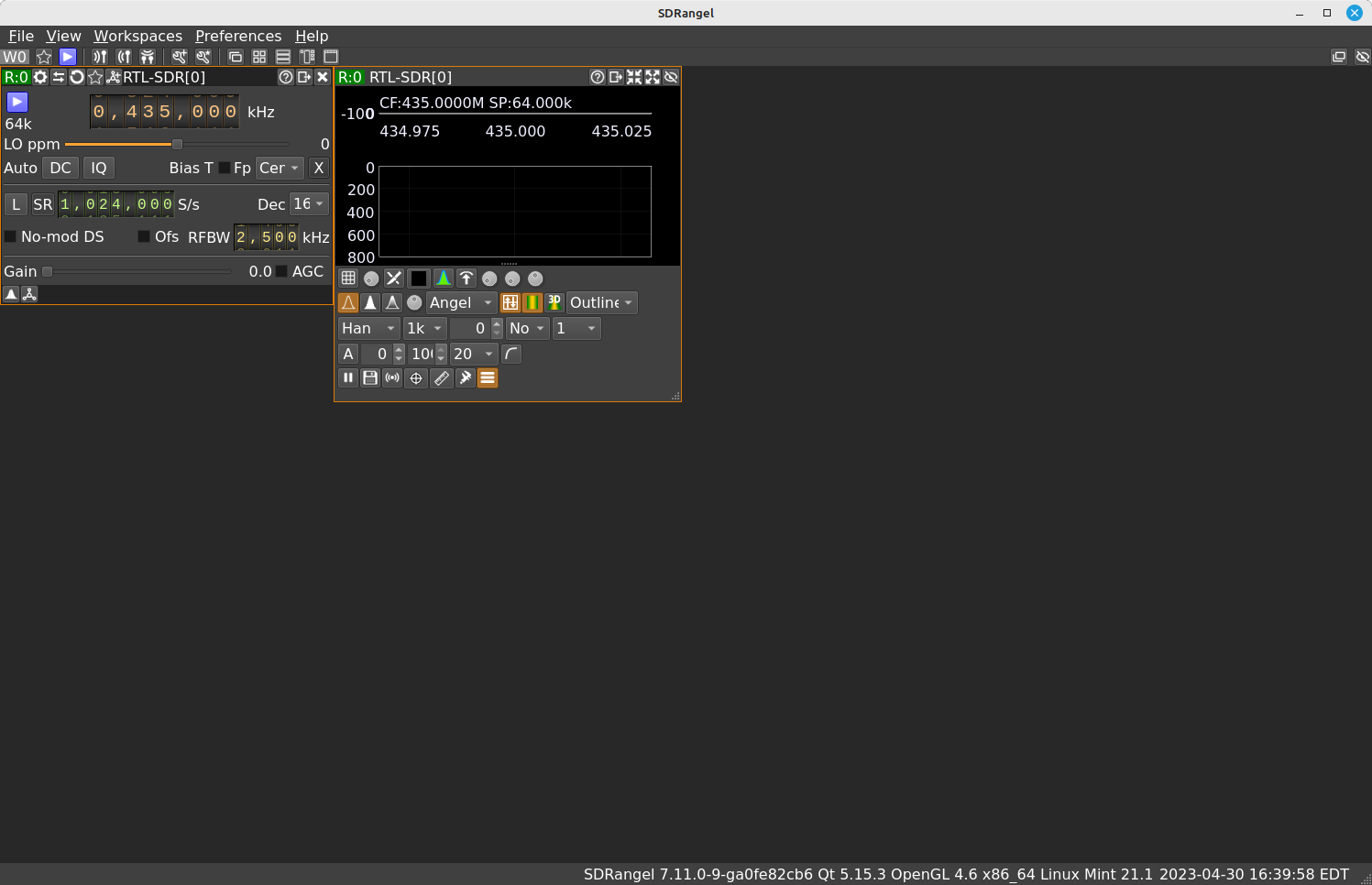
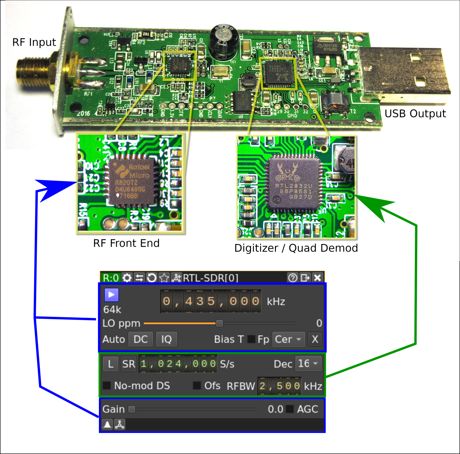
The window in the upper, left will control the actual hardware. For the RTL-SDR, here's an overview of what those settings will control.
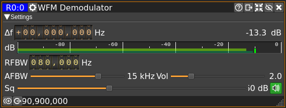
The window on the right, the one with the spectral displays, is quite small, and doesn't really show the displays large enough to be useful (in my opinion). I recommend that you click on the icon labeled as "Stack sub windows in columns". This will place the windows (probably) as shown below.
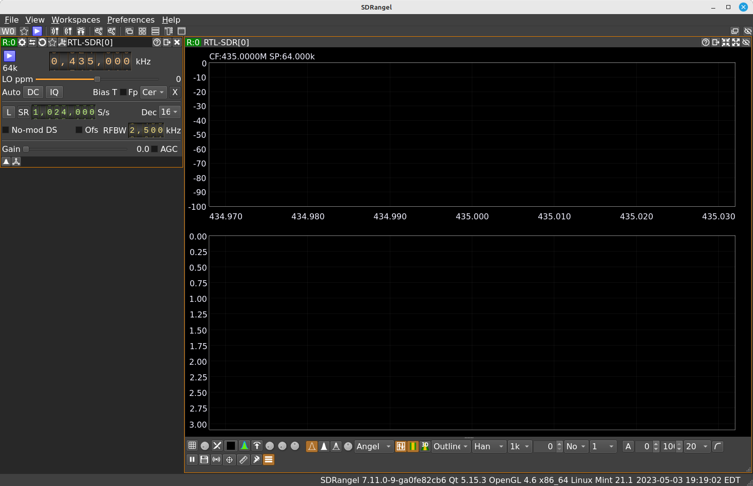
Time to kick things off. Press the blue arrow key. This is the "Start/Stop Acquisition" button and will toggle the SDR on or off.
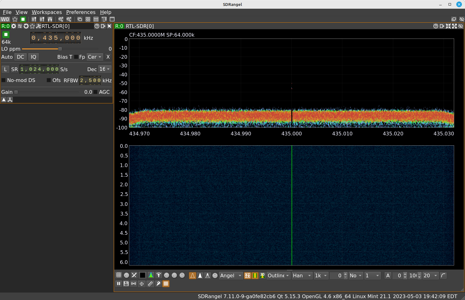
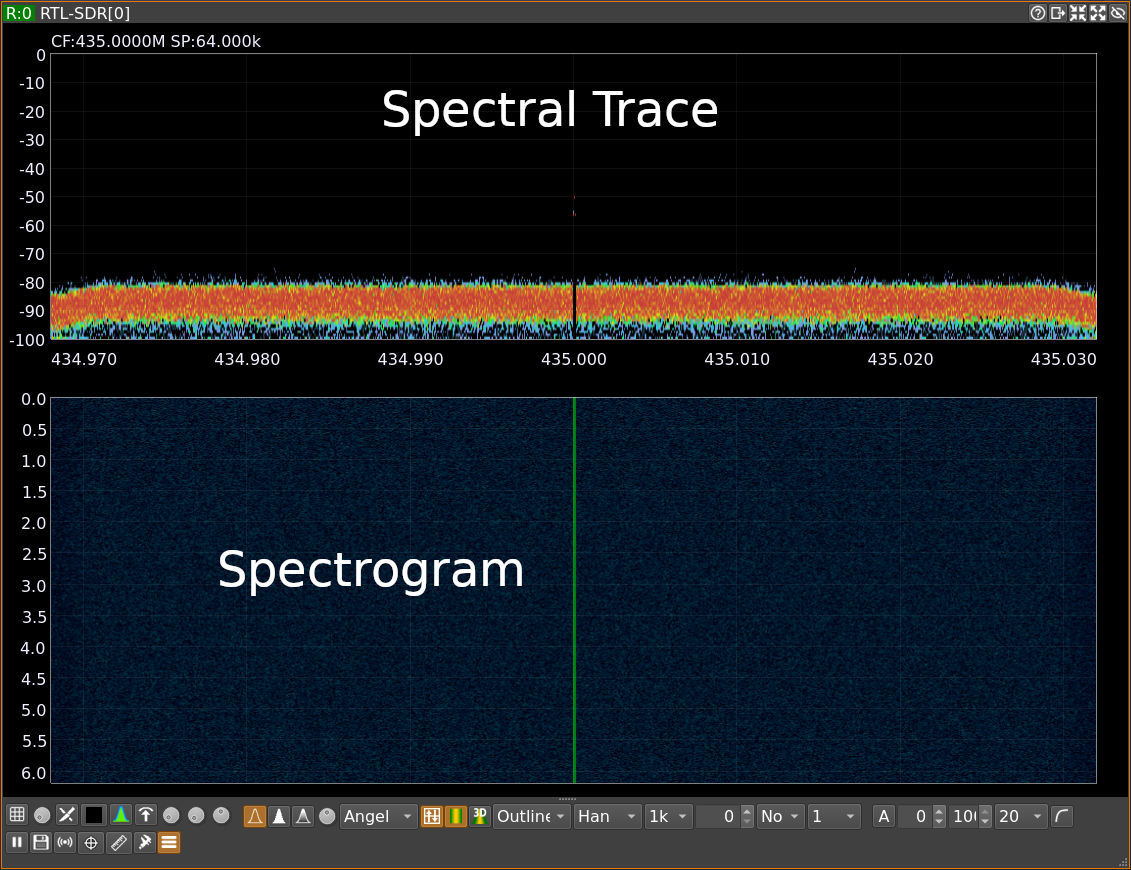
At this point, you have a running SDR that is collecting samples and sending them to your computer. The spectral trace and spectrogram show you all of the signals available within your instantaneous or stare bandwidth. This is the full bandwidth that can be used to demodulate a signal, or multiple signals, at one time.
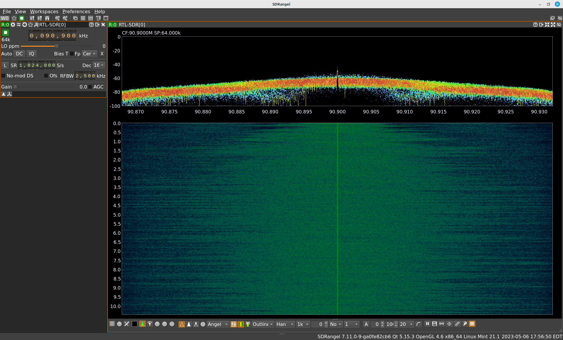
I want to see some signals. I'm going to tune to the FM broadcast band. Specifically, I'm going to select some classical music stations centered around 90.9 MHz.
Setting the Sample Rate
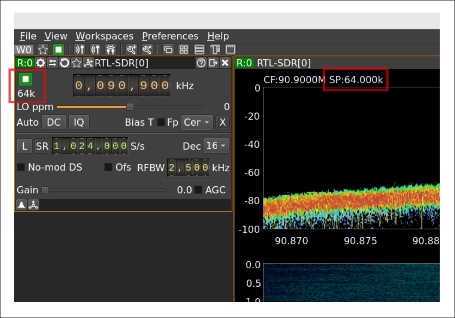
SDRangel is currently set to a sample rate of 64 kHz. This is shown in two places. One is in the control window, just below the "Start/Stop Acquisition" button. The other place is at the top of the spectral display window.
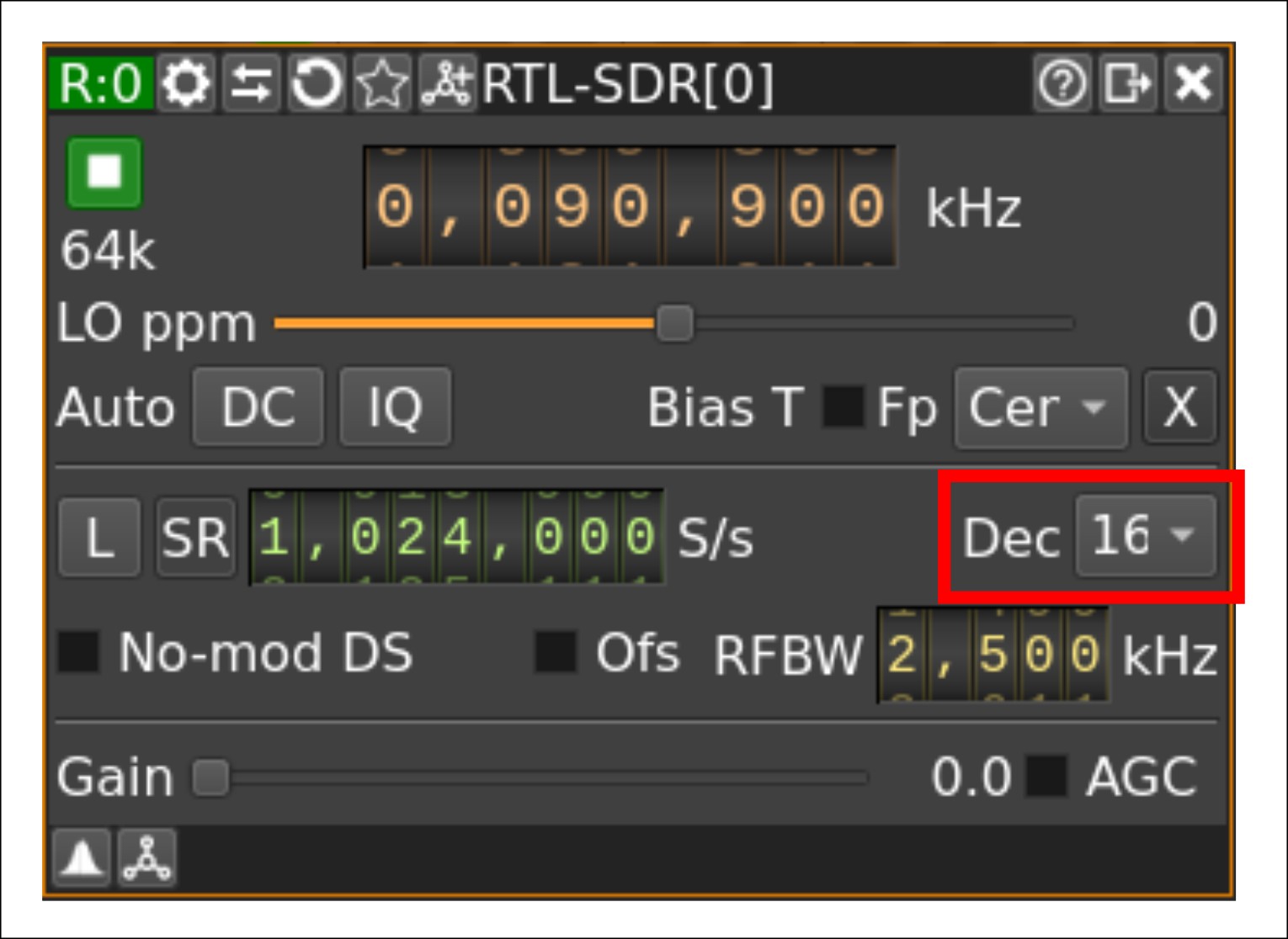
This program lets you set the sample rate by both setting a certain sample rate plus a decimation value. The sample rate itself should set the actual sample rate of the digitizer within the hardware. The decimation value is (most likely) done in software within SDRangel once it receives the samples from the hardware. Now, you might asking, "Why do this two-step? Why not just set the sample rate to whatever you desire?" The reason is that most hardware has fixed limits on the sample rate you can set. The RTL-SDRs, for example, are limited to values within two ranges (225.001 kHz - 300 kHz, 900.001 kHz - 3.2 MHz). If you try to set the sample rate to 400 kHz, for example, the RTL-SDR would say, "No." SDRangel gives you a work-around for this. The RTL-SDR does allow for a 1.6 MHz sample rate. We could set the sample rate to 1.6 MHz, then decimate by 4. This would give us a 400 kHz sample rate. Again, just an example.
A major rule of digital signal processing is that the complex sample rate must be greater than the bandwidth of the signal being processed.
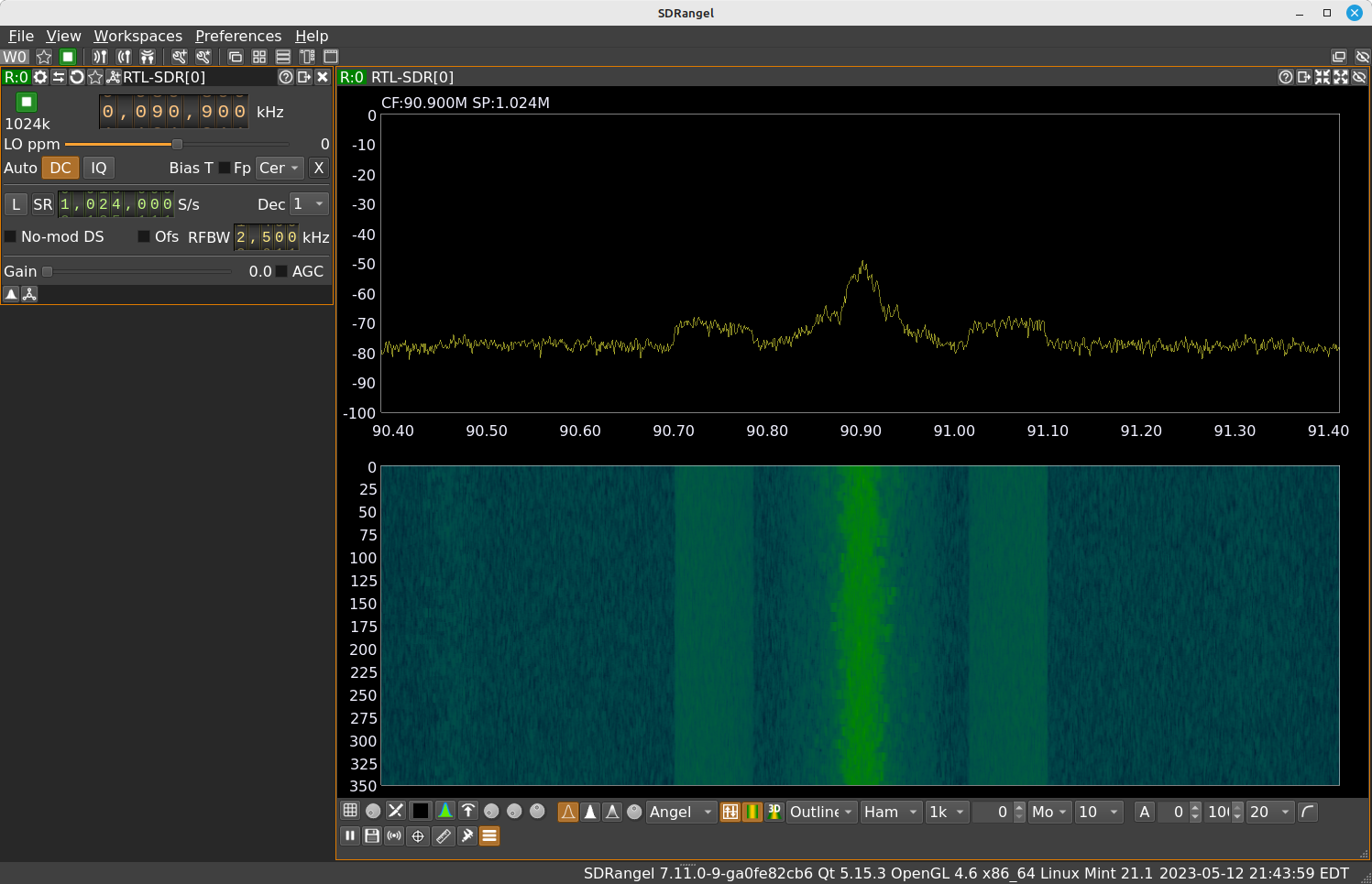
A major rule of digital signal processing is that the complex sample rate must be greater than the bandwidth of the signal being processed. Right now, our sample rate is 64 kHz. I'm trying to process a FM broadcast signal. That requires roughly 200 kHz of bandwidth. I need to either raise the sample rate or lower the decimation value. Or a combination of the two. SDRangel only allows decimation values that are powers of 2. By lowering the decimation value to 4, the sample rate will be 1024 kHz / 4 = 256 kHz. This is greater than the bandwidth. It will be plenty for processing this signal.
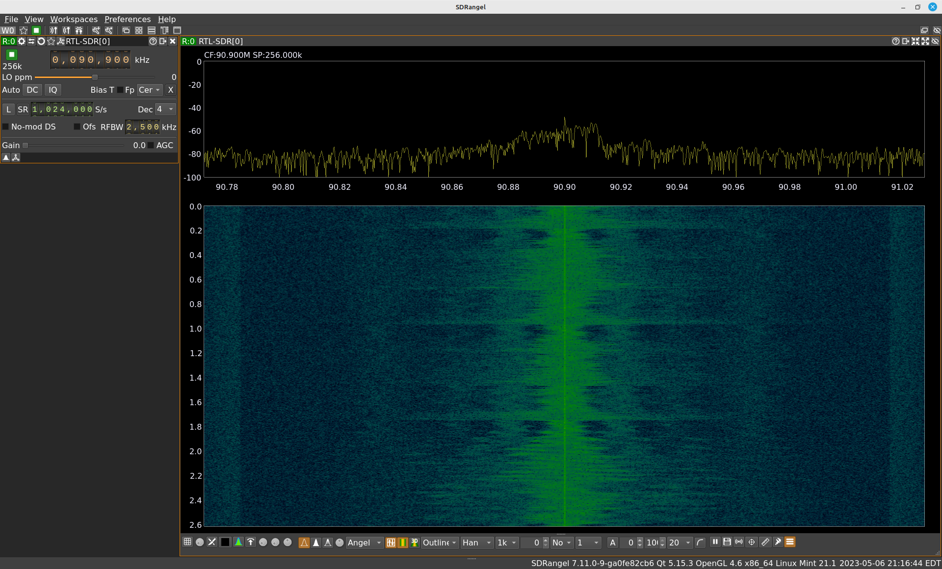
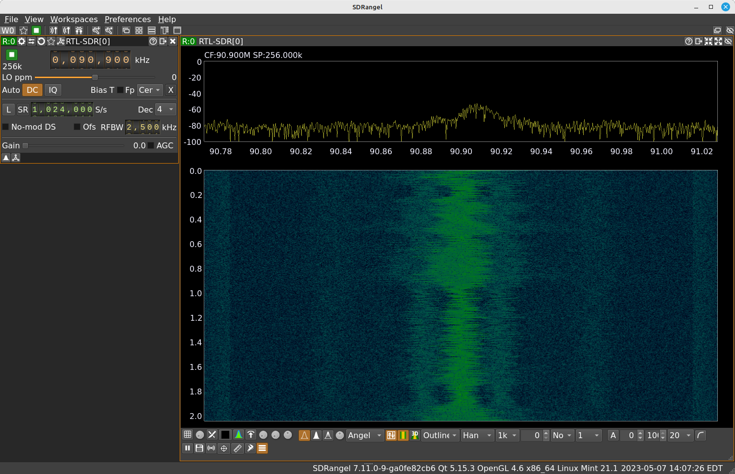
Note that spectral line at the center of the spectral display above. That's due to something called "DC leakage" or "LO feedthrough". It's a problem created between the RF front end and the quadrature demodulator circuit. To get rid of it, SDRangel provides a button marked (appropriately enough) "DC". Pressing that button will eliminate most, if not all, of this.
Setting the Gain
You want the signal to take up as many of levels of the quantizer as possible without going over.
Gain can be easily misunderstood. Yes, it amplifies the signal. It's not a case of "more is always better". Don't just crank it up to the max and think, "It's good!" There's also a thing called "too much gain". The gain, in this case, controls how much signal level gets to the digitizer. One of the main components of a digitizer is a quantizer. The quantizer converts the analog amplitude into a set of digital bits. Every quantizer has a maximum number. The RTL-SDR uses 8 bits. 28 = 256 levels. This means each sample will be forced to fit to one of those 256 levels. You can't over 256. You want the signal to take up as many of those levels as possible without going over. That's right. Setting the amplitude going into the quantizer is like guessing the value on "The Price is Right". Get as close as possible, but don't go over.
Let me just get this out of the way. DO NOT SELECT AUTOMATIC GAIN CONTROL!
Let me just get this out of the way. DO NOT SELECT AUTOMATIC GAIN CONTROL! I've never gotten it to work reliably. This is not a slam on SDRangel. NO one's SDR software gets AGC correct. Why? No idea. It just doesn't work. Instead, I'm going to show you how to set it properly manually.
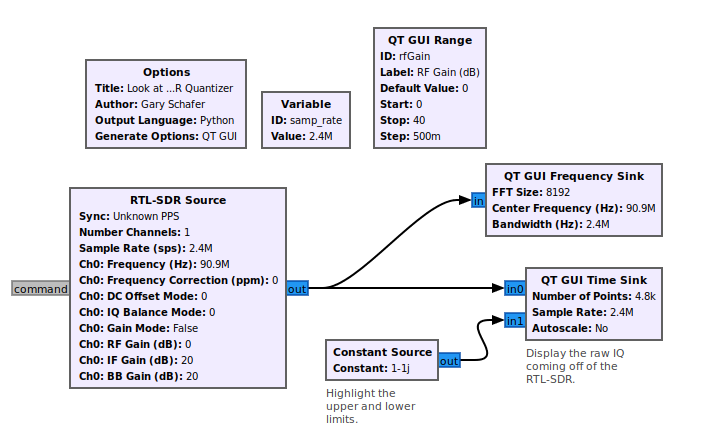
How do you do that? How do you set the gain so that you're covering as much of the quantizer as possible, but without overdoing it? If we were using Gnu Radio Companion, it would be pretty straightforward. With a RTL-SDR, the optimal gain is achieved when the raw IQ out of the SDR going into a time sink has the levels set just below +/- 1.
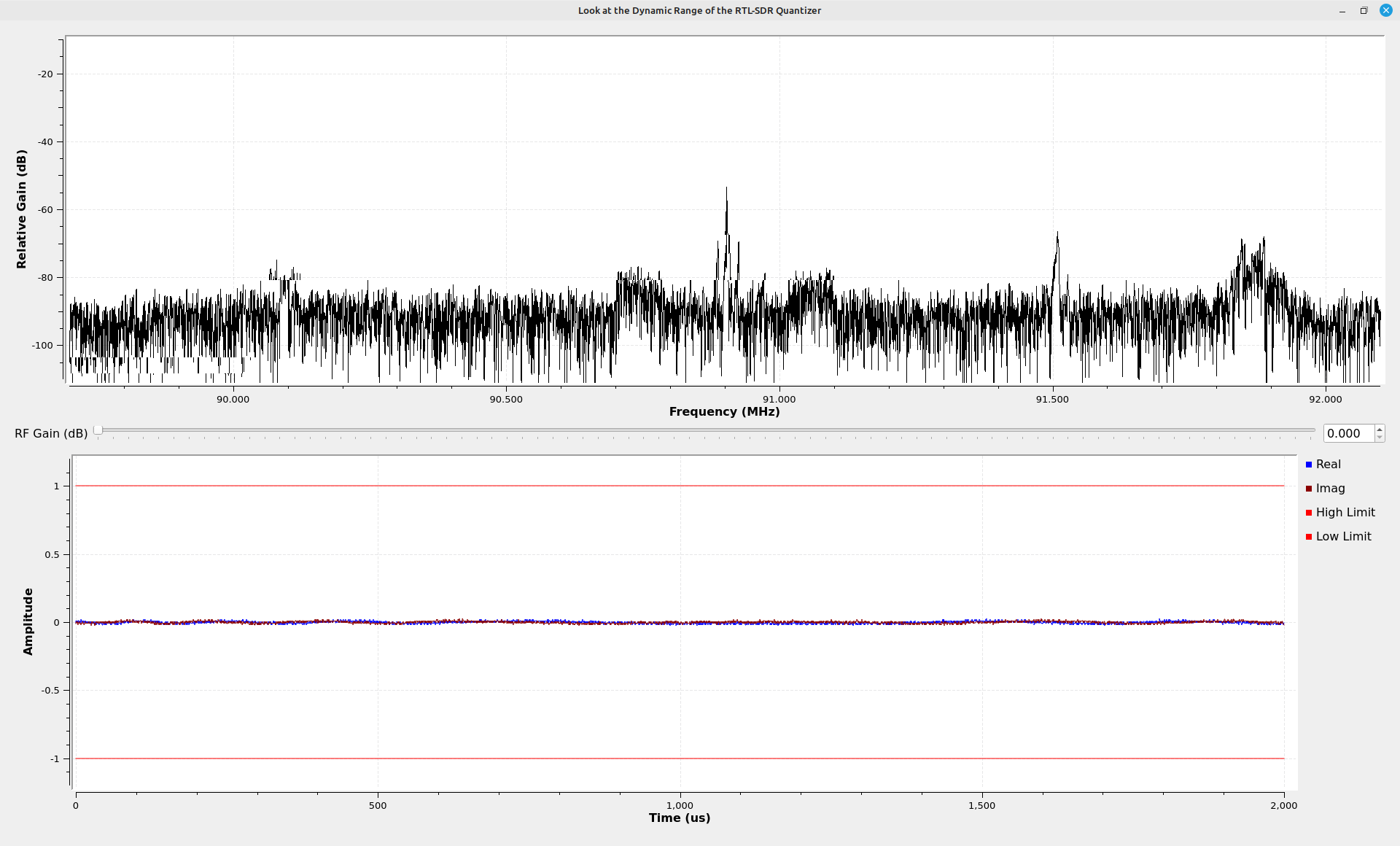
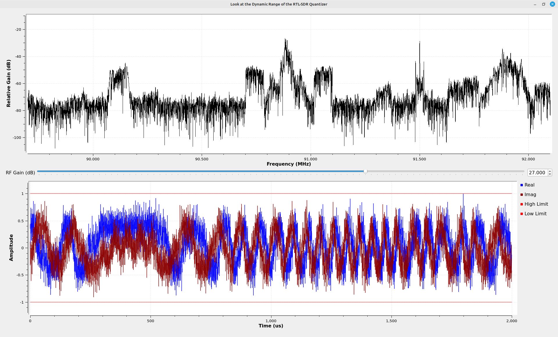
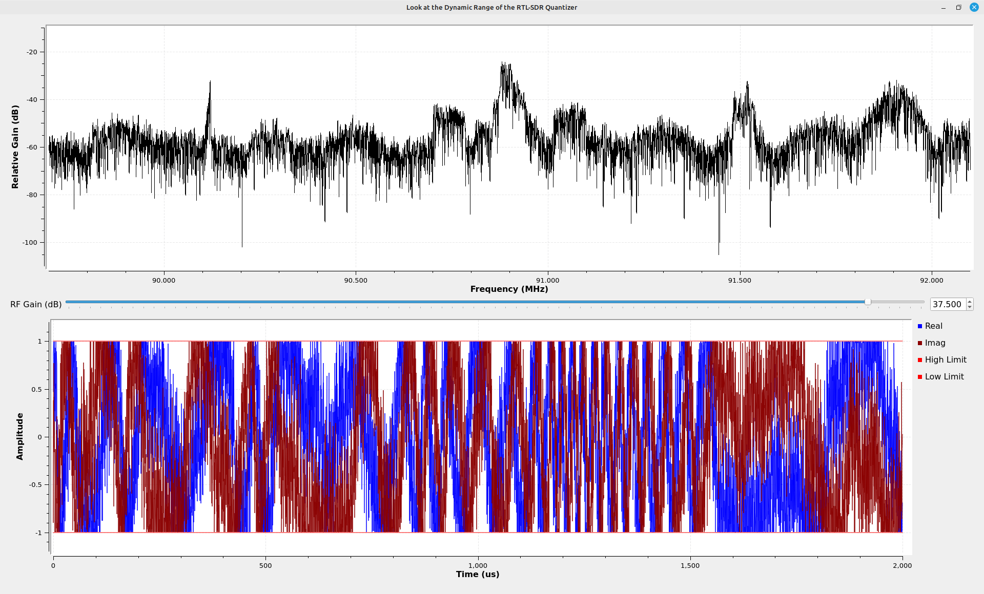
The problem is that SDRangel does not provide a means to look at the IQ time domain samples unfiltered. The best that is available is to use the receiver control spectral displays. This requires a bit of experience to set correctly. In the end, so long as the signal you're trying to receive sounds correct, or it provides the information in which you are interested, then your gain is good enough.
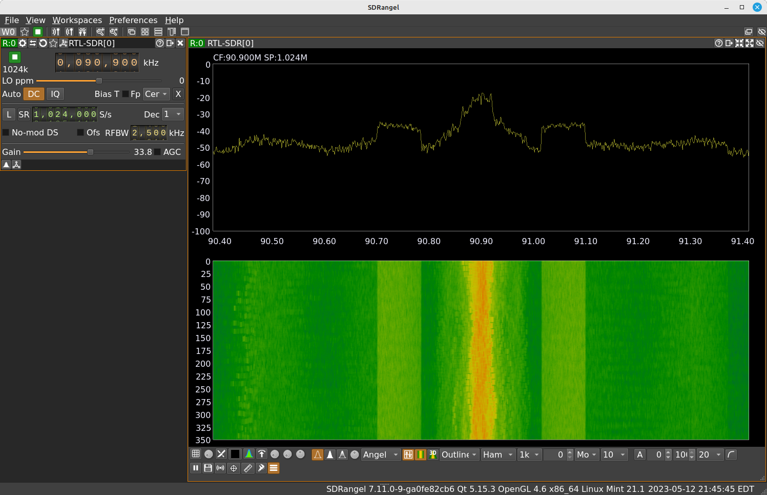
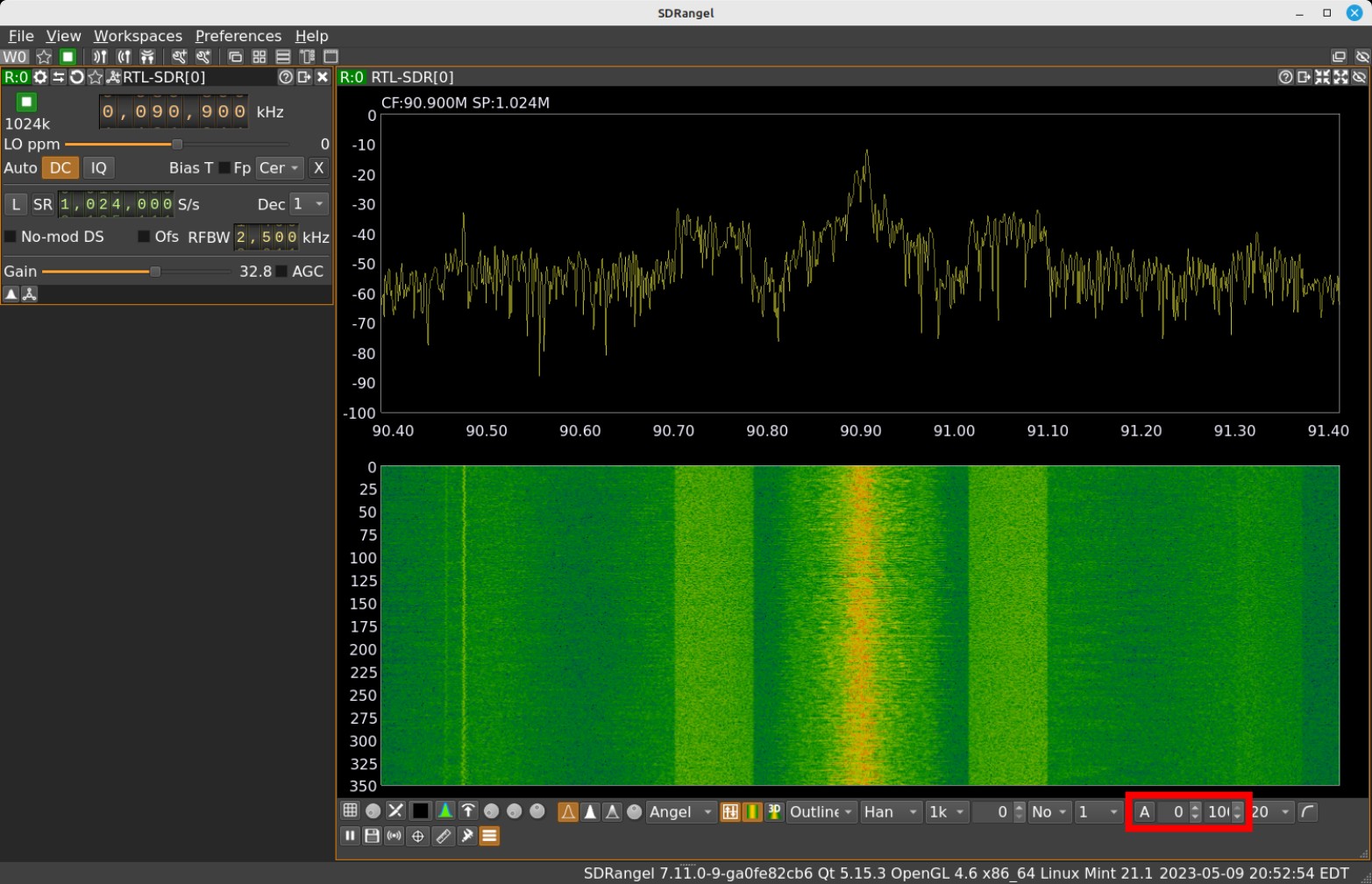
Setting the Display Scales
I prefer to look at spectral displays with the amplitude scales properly set. For SDRangel, this means setting the reference level and range. These controls are at the bottom of the spectral displays. Fortunately, SDRangel makes this pretty simple using it's "Autoscale" button. Pressing this icon automatically adjusts the reference level and ranges to pretty much what I would have selected if I did it manually. I can also tweak either setting if I don't like how it looks.
Demodulating and Processing a Signal
Once you have a radio sending samples to SDRangel, SDRangel can further process the samples. The only processing that has been done thus far is to create some spectral displays. If I were to replicate this in Gnu Radio Companion (GRC), it would look something like this:
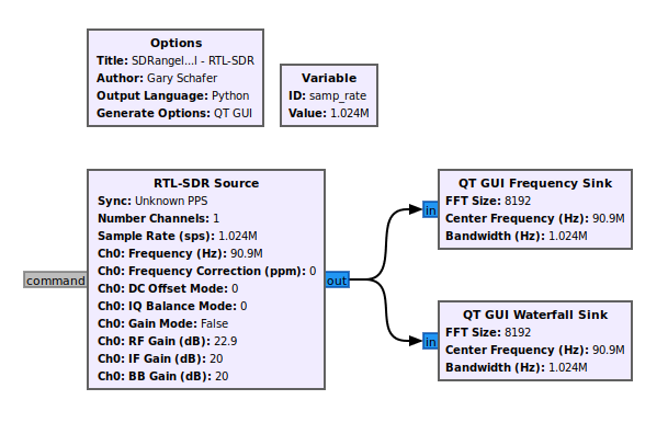
You've not demodulated or decoded anything. There are some basic steps that you have to do next. Those steps are (in order):
- Center the signal: The first step of processing signals that are in complex format is to center them at 0 Hz. NOTE: This does not mean that the signal has to be centered in the spectrum in order for SDRangel to demodulate and process it.
- Filter the signal: You want to filter the signal so that only that one signal is left. All other signals and noise needs to be removed.
- Demodulate the signal: At this point, you can demodulate the signal.
- Process the demodulated signal: This includes any post processing required for baseband signals, either analog or digital, to recover whatever information is on it. For example, this might be the stereo signal or RDS from a FM broadcast station, or the digital video stream from an over-the-air television broadcast station.
Let me show you what I mean using the signal that is currently displayed on SDRangel's spectral displays. I have a FM broadcast signal at the center of my spectrum.
Adding a Channel
SDRangel uses the terms of "radio" and "channel". The "radio" is what provides the samples to the computer. The "channel" is where SDRangel centers, filters, demodulates and processes the signal.
To perform the steps I outlined above, SDRangel creates a channel. SDRangel uses the terms "radio" and "channel". The "radio" is what provides the samples to the computer. The "channel" is where SDRangel centers, filters, demodulates and processes a signal. I'm going to add a "channel" here to demodulate this FM station. The "channel" options are opened by clicking on the "channel" icon at the top of the receiver control window. Clicking on this icon opens a window that lists allllllllllll of the available demodulation and processing options.
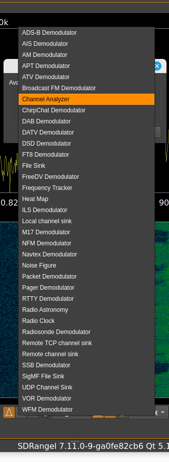
I first selected "NFM Demodulator". (NOTE: For those of you wondering, "Why not use the 'Broadcast FM Demodulator', I'm getting to it. Be patient.) "NFM" stands for "narrowband frequency modulation". When it comes to FM, there's a tendency to think in terms of "narrowband" and "wideband". FM deviates the carrier above and below its center frequency. The difference between "narrowband" and "wideband" has to do with the ratio of the maximum modulation frequency to the deviation of the carrier. This ratio is typically called the modulation index. If that index is less than 1, it's narrowband; one or greater is wideband. Frankly, nowadays, I find that distinction more annoying than anything. I believe it made a difference in the days of analog circuitry because it meant you could use different circuits. Made them more economical. Nowadays, with digital processing, FM is FM. Modulation index doesn't enter into it.
ANYWAY, I selected "NFM Demodulator". It sounded like crap. The NFM did not provide enough bandwidth. The maximum is 40 kHz. FM broadcast here in the good, ole US of A is 180-ish kHz. If you filter too much of a signal, you distort it. That's what happened here. It sounded like crap. Yes, it demodulated. But demodulating a 180 kHz wide signal with a 40 kHz filter means most of the signal is removed.
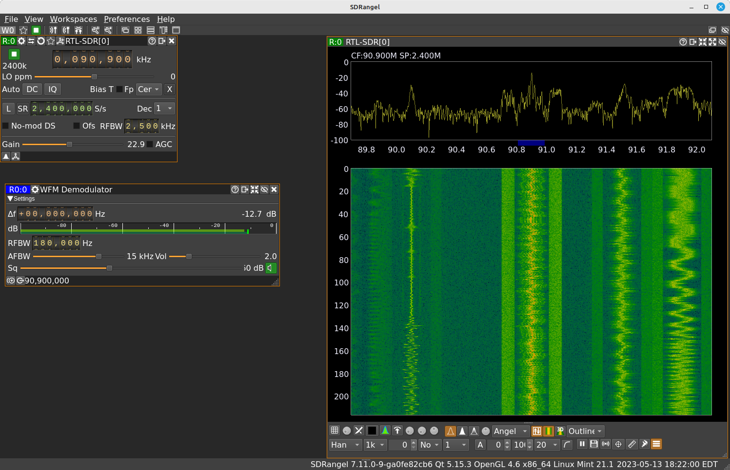
Moving on, I next tried the "WFM Demodulator". "WFM" means (as you may have guessed) "wideband frequency modulation". Let's take a look at what this "channel" does for us. As I said, we need to center a signal, filter it, demodulate it, then process the demodulated signal. When you first add a "channel", it sets the offset from the center of the spectrum to 0, filters it, demodulates it, and presents the information to the user. This latter part might be sending audio to the speakers or giving you a real-time map of airplanes in the area.
Opening the "WFM Demodulator" channel shows as a blue band in the center of the spectrum. The width of the band shows the amount of signal that is being allowed to pass through. Anything not inside of the band is being filtered out.
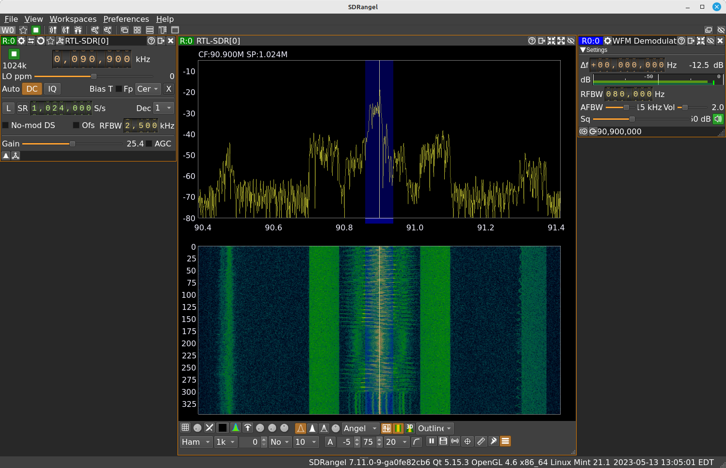
Let's take a look at the controls. You'll see many of the same controls regardless of the "channel" type you select. The top, left corner shows "R0:0". This is the "radio / channel" model that SDRangel uses. The first "R0" means that this channel is operating on the samples coming from "R0". That's my RTL-SDR. The ":0" means that this is the first channel operating on the samples from "R0". At the top of the window is frequency offset, denoted by "Δf". This sets the placement of the channel within the span denoted in the spectral displays. This gives you the ability to control which signal you'll process. This frequency offset occurs solely within software; it has no effect on the center frequency of the SDR hardware. The frequency offset occurs only on the samples coming off of the SDR. This means it's limited to whatever is within the spectral display. Below the frequency offset is a "dB" meter. This gives you an idea of signal level. Note that this is not an absolute level, such as dBm or dBW. The other, important control here is the "RFBW" (RF bandwidth). This is set to 80 kHz. Broadcast FM here in the US is 180 kHz. The audio sounds distorted, as it should be. By adjusting the bandwidth up to 180 kHz, the output audio sounds fine. I'm receiving the L+R baseband channel that extends from 0 - 15 kHz in all FM broadcast stations.
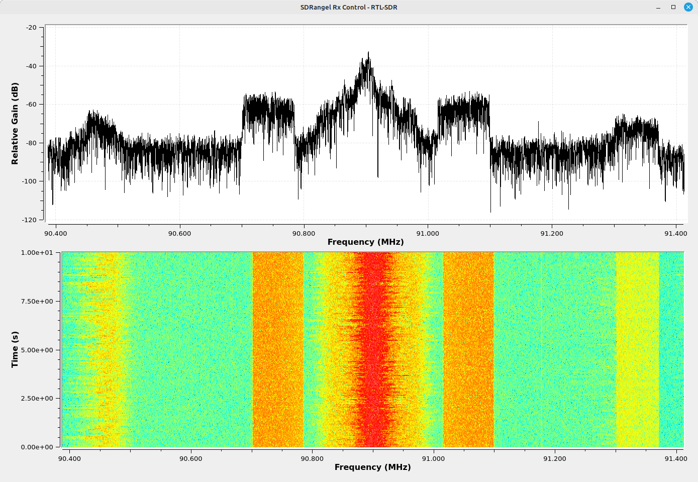
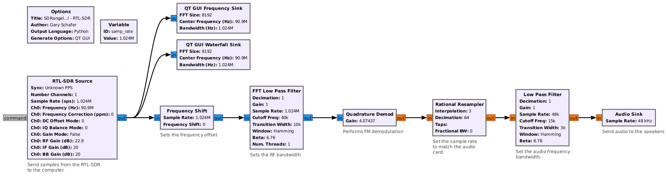
If I were to create a similar capability in Gnu Radio Companion, it would look something like this flowgraph.
Before continuing on, I'm going to increase the sample rate. I want to have more signals within my spectral display so that I can have multiple channels running. (Yes, I have a signal at the left edge of my display, but it's not ideal.) Increasing my sample rate to 2.4 MHz, I get the following spectrum.
Now I'm going to add another channel, this time a "Broadcast FM Demodulator". Once again, I click on the "Add channels" icon in the receiver control window. I get the list of options, and select "Broadcast FM Demodulator". I get a larger window than with the "WFM Demodulator".
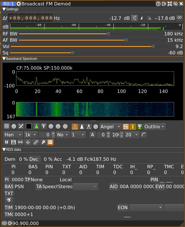
The difference between the "WFM Demodulator" and the "Broadcast FM Demodulator" is that the latter can demodulate the stereo subcarrier at 38 kHz (assuming there is one), add a deemphasis filter to the L and R audio signals, and demodulate and decode (theoretically) the RDS signal at 57 kHz. The WFM signal, when applied to a broadcast FM signal, would only be able to deal with the baseband signal. The WFM demodulator, however, would be able to handle any wideband FM signal. The broadcast FM demodulator is only set for broadcast FM signals. Any other type of FM signals may be a problem.
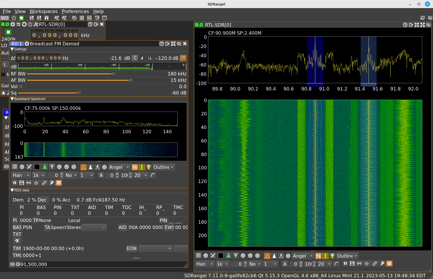
I want you to understand what's happening here. The "radio" (an RTL-SDR, in this instance) is feeding samples covering a certain amount of bandwidth to SDRangel. Right now, I'm feeding 2.4 MHz of bandwidth to SDRangel. There are 4 signals within that 2.4 MHz bandwidth centered on 90.9 MHz. I can add "channels" to demodulate each one separately. The "channels" operate on the samples fed from the SDR; the "channels" have no direct control on the SDR itself. Once the samples are fed to a "channel", all I have to worry about is whether I have the processing power to process the signals in each channel.
I'm going to set the frequency offset of the broadcast FM demodulator to cover one of the other signals in the spectral display. Using my cursor over the 100 kHz position, I adjusted the frequency to 600 kHz. Here's how my display looks now.
Trying the ADS-B Demodulator
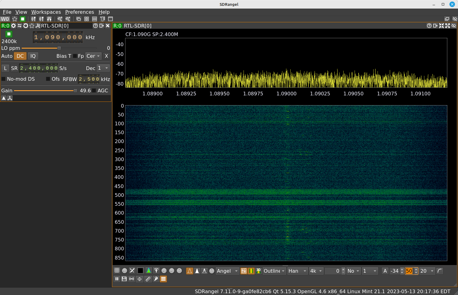
Let's try a different demodulator. Let's try the ADS-B channel. That means having the tune the SDR to a different frequency. ADS-B is centered on 1090 MHz (mostly). First, I closed the two, current channels that were running (the "WFM Demodulator" and the "Broadcast FM Demodulator"). I set the receiver control to 1090 MHz (1,090,000 kHz). This gave me a flat spectrum. ADS-B is not typically going to be a strong signal. I'm picking it up from a discone in my attic. The signal will not be strong regardless. This means I need to crank the gain. TO THE MAX!
ADS-B is a pulsed transmission system. The best way (IMO) to see the pulses is to look at the amplitude demodulated time domain. There's only one way in SDRangel to see such a display. That's with the "Channel Analyzer" channel. Selecting "Add channel" from the receiver control window, I selected "Channel Analyzer". I went ahead and maximized it in SDRangel. I don't need the spectral display, so I minimized the "Channel Spectrum" portion of the window. I also maximized the "BP" (bandpass) setting to give me the full bandwidth of the SDR. ADS-B primary bandwidth is roughly 3 MHz. Might as well max out the bandwidth if all I have is 2.4 MHz.
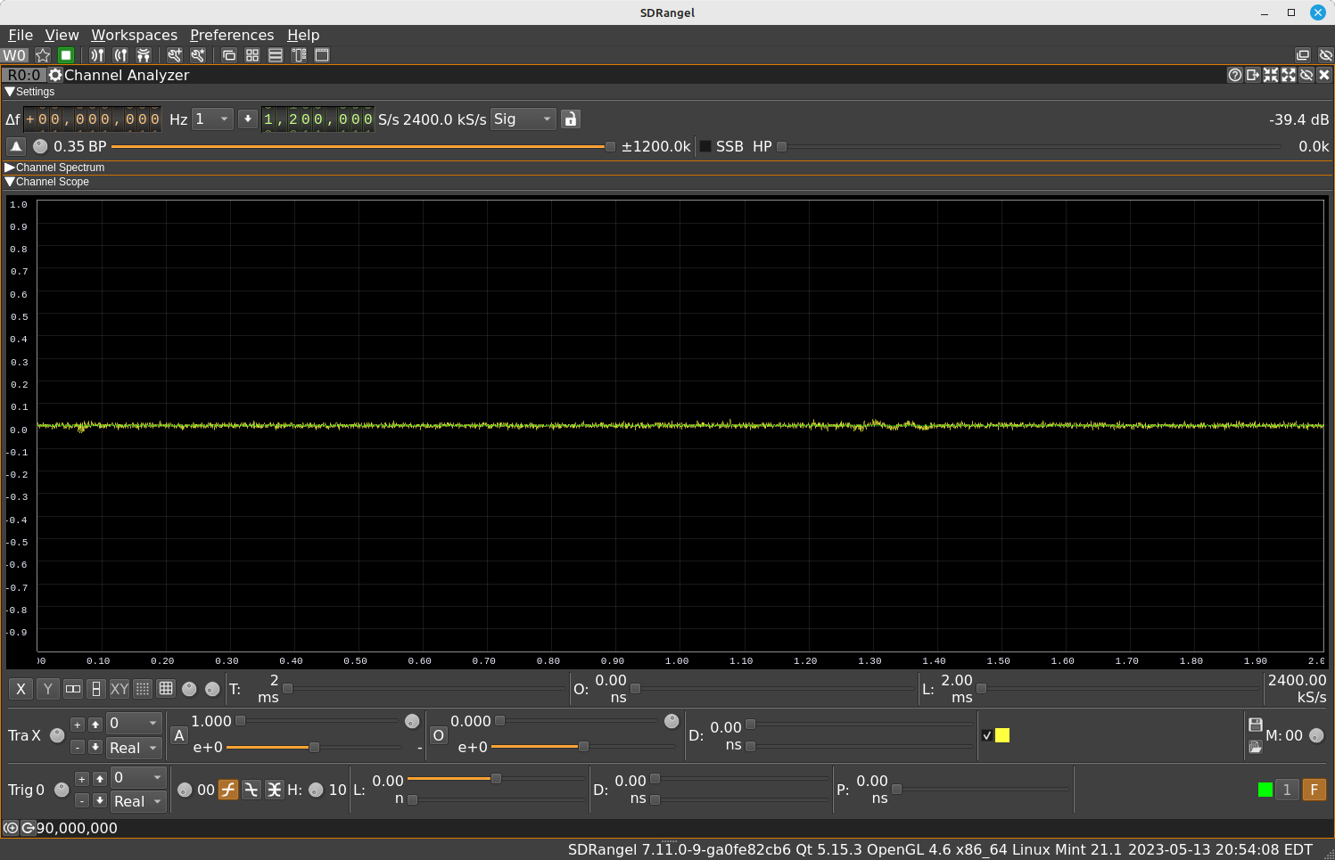
Let's talk about the time domain display. This is what many people call an oscilloscope or just o-scope. Frankly, the controls here leave a lot to be desired. An oscillscope has a couple of basic settings. These are the amplitude setting (controls the vertical axis), the time setting (controls the horizontal axis), and a trigger (controls when the system actually creates a trace). Trying to figure out how SDRangel performs each of these tasks is... daunting. When you first activate the "Channel Analyzer", the trigger is set to "free run". This means its just gonna create traces as fast as it can regardless of what is happening with the signal itself. I want to trigger on the actual pulses. To actually activate the trigger, I clicked on the "F" icon in the lower, righthand corner. After messing around with the different controls, I finally managed to capture a burst.
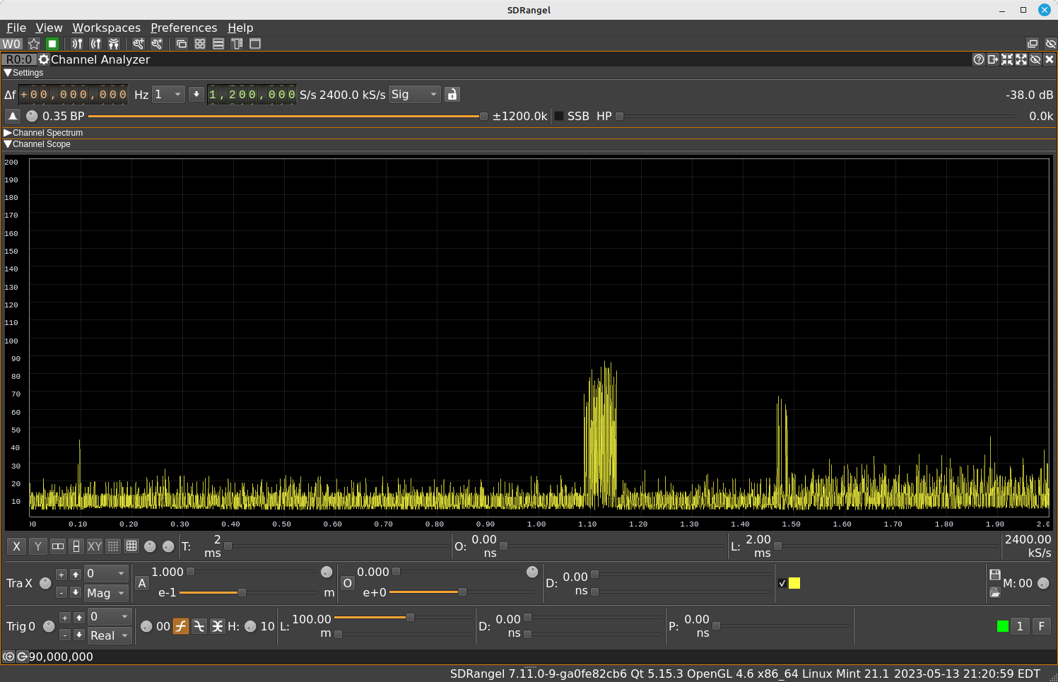
Frankly, it dawned on me that this display alone will require its own blog post. Maybe later.
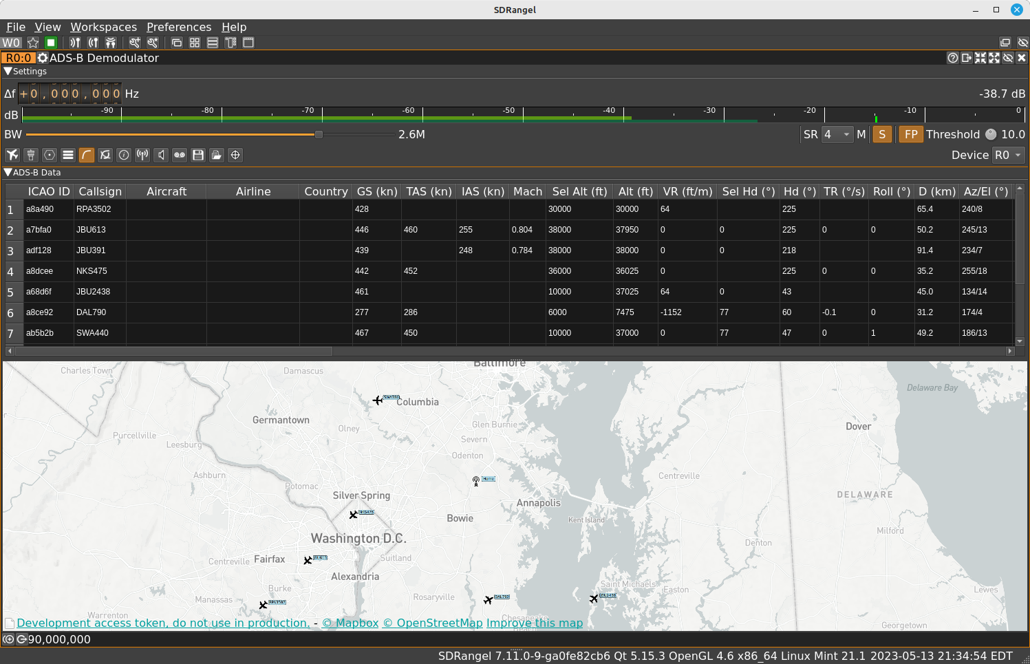
Closing the "Channel Analyzer", I clicked on "Add channel", then selected the "ADS-B Demodulator". This selection is more than a demodulator. It's also a decoder. ADS-B uses pulses that are modulated onto the carrier using on-off keying (OOK). Once the SDRangel demodulator has demodulated the pulses from the carrier, it also decodes the pulses to extract the information they carry. SDRangel further posts this information onto a map showing the aircraft whose information it has gathered and decoded. This is one of the best ADS-B systems I've seen without having to go to websites such as flightradar24.com or flightaware.com
Once I had the ADS-B demodulator running for awhile (tens of minutes), and I tried to close it, SDRangel crashed. This happened more than once. I'm figuring its another bug.
I think that's enough for now. This has already turned into a major wall of text and images. I may come back to SDRangel at some point in the future. Most likely, I'll take a look at some of the other SDR programs, such as SDR# or SDRConsole. In the meantime, if you're using SDRangel, just remember that it consists of a "radio" (getting samples from the antenna into your computer) followed by "channels" (actually processing some or all of the samples coming in).
Enjoy!
SDR Radio Doesn't Show on Rx Device List
This happened to me. As I was putting together this blog post, I made sure my RTL-SDR was plugged in, started SDRangel, clicked on the "Add Rx Device" icon, then checked the dropdown list. There was no RTL-SDR hardware listed. Weird. Restarted SDRangel. Still no RTL-SDR listed. Rebooted the computer. Still the same. It wasn't until I did a web search that I discovered the problem. SDRangel already had a window opened for my RTL-SDR. Here's a quick test to tell. Look at the SDRangel window. If you see scroll bars on the bottom and/or sides, then you have windows opened somewhere. The quick solution? Press one of the "Windows" icons at the far right of the workspace icons in SDRangel. There's an icon for "Cascade", one for "Tile", two for "Stack" (one vertical and one horizontal), and an icon to open each window in its own tab. If you press one of those icons and your SDR control window shows up, there you go. Problem solved.