
Random Quote Board
Improvement to the Zero Crossing FM Discriminator
A few years ago, I wrote a post on creating a zero crossing FM discriminator. At the time, I wrote:
Much to my surprise, this GRC graph actually works. One thing I noticed was that there was a distinctive crackling in the background.
Just to review, here's the original flowgraph.
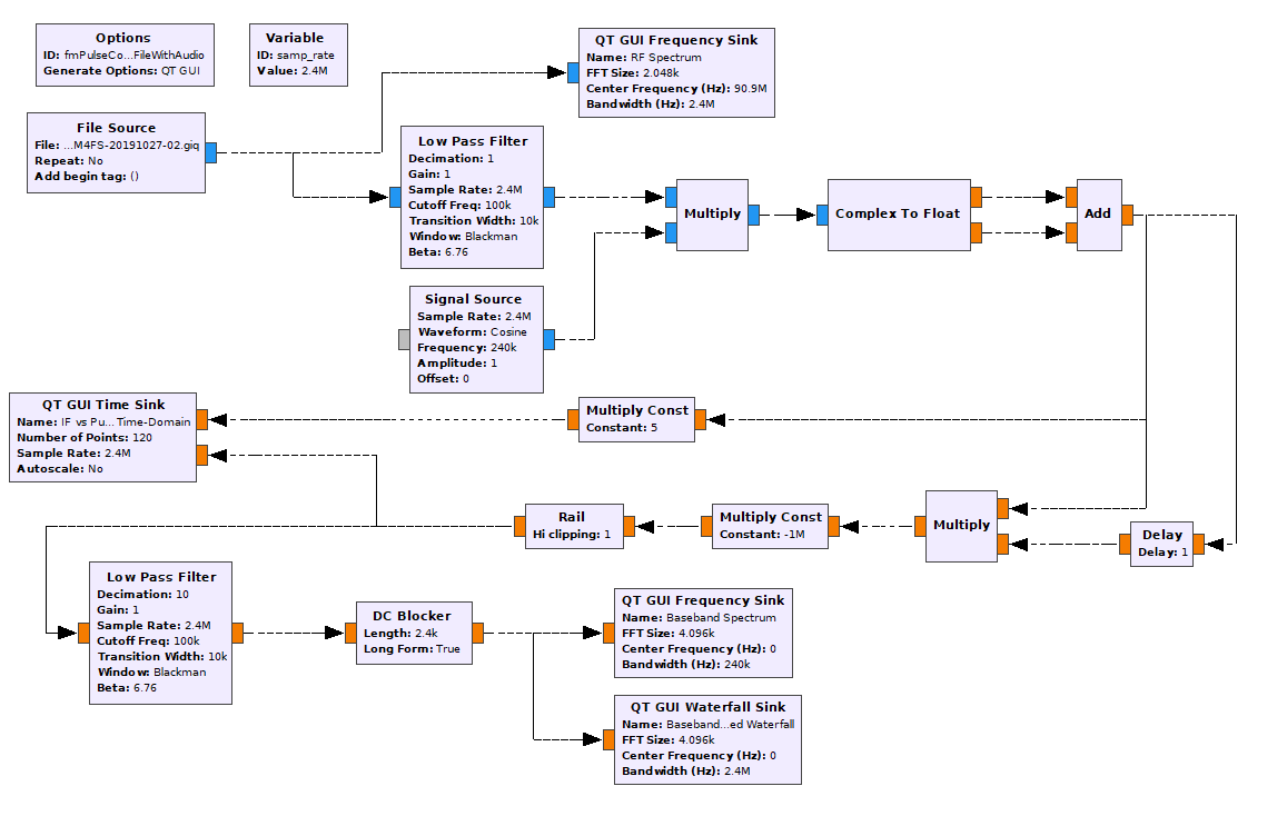
I'll boil it down to the absolute basics of this circuit:
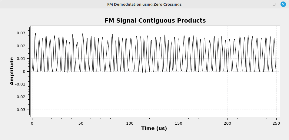
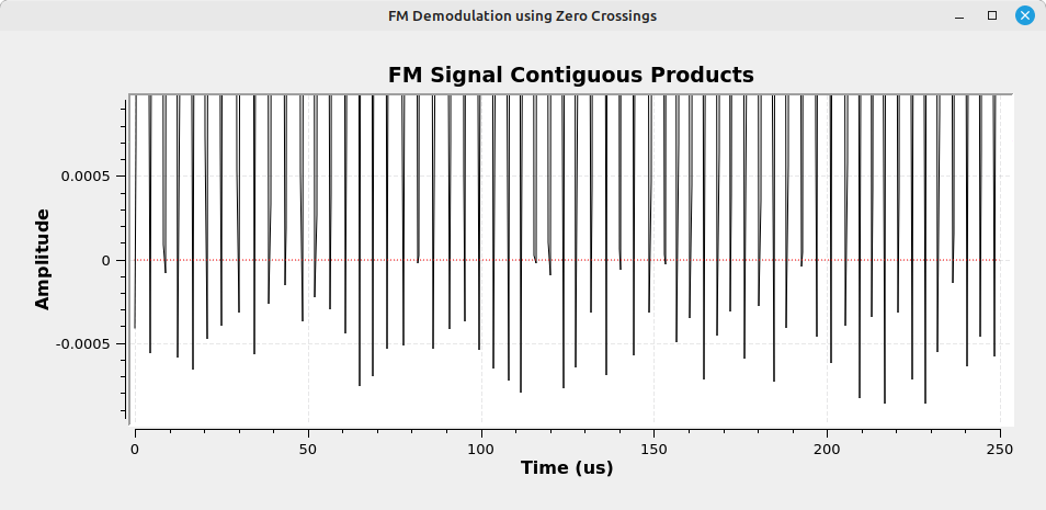
- Multiply each sample by the sample just before it. The product samples will either be negative or positive. A negative value means a zero crossing. All other samples (the positive-valued ones) will not be zero crossings.
- Convert each negative-valued sample into an impulse with a value of 1.
At this point, the signal is effectively demodulated. It simply needs to be filtered, and the sample rate adjusted for the desired endpoint. For example, in this case, the endpoint is my audio card.
I hypothesized that that crackling may be due to the sample rate and the number of impulses created per cycle of the frequency modulated sinusoid. Now, I have a different hypothesis. I think its due to my multiplying the product samples by -1 million. It's not the negative part that's the problem; the problem is the multiplication by 1 million. I was trying to make impulses by multiplying by a large number, then using the "Rail" block to limit each value to 1. Well, multiplying each sample by a million also means I'm amplifying the background noise as well. It's like RF 101. All amplifiers (and that's what that multiplication is doing) add noise. In this case, it didn't add noise, it simply amplified it and made it more pronounced.
Then I learned of the "Binary Slicer" block. It appears to work as follows: Any input value that is zero or greater is set to 1; all other values are set to 0. Given that the input samples are floating point, this is probably a fairly simple block. Look at the sign bit; if the bit is 0 (meaning the value is positive), set the output to 1. If the sign bit is 1 (meaning the value is negative), set the output to 0. Unlike my use of the "Multiply Const" and "Rail" blocks, the "Binary Slicer" block creates impulses without changing the original values. Here's a revised flowgraph in which the "Multiply Const" and "Rail" blocks are replaced with a "Binary Slicer" block.
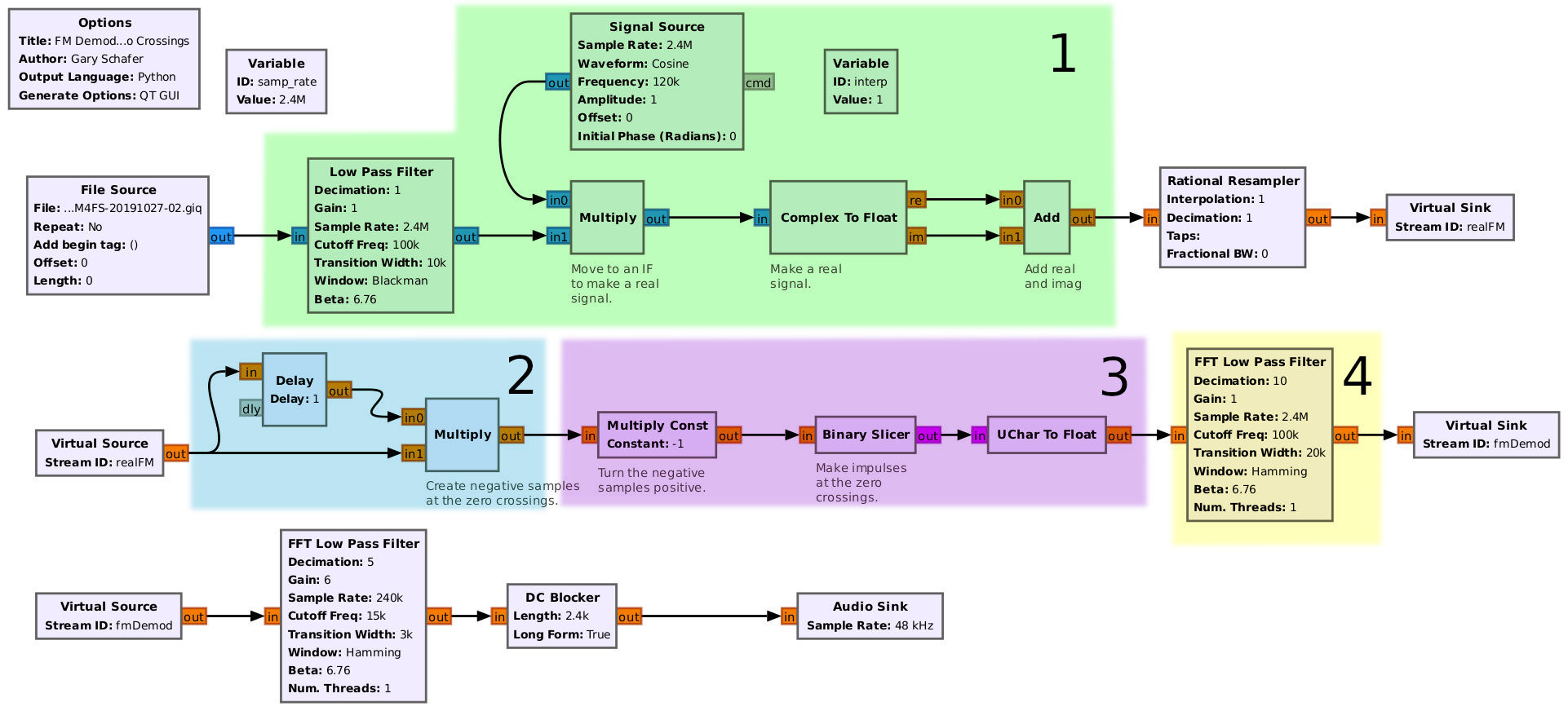
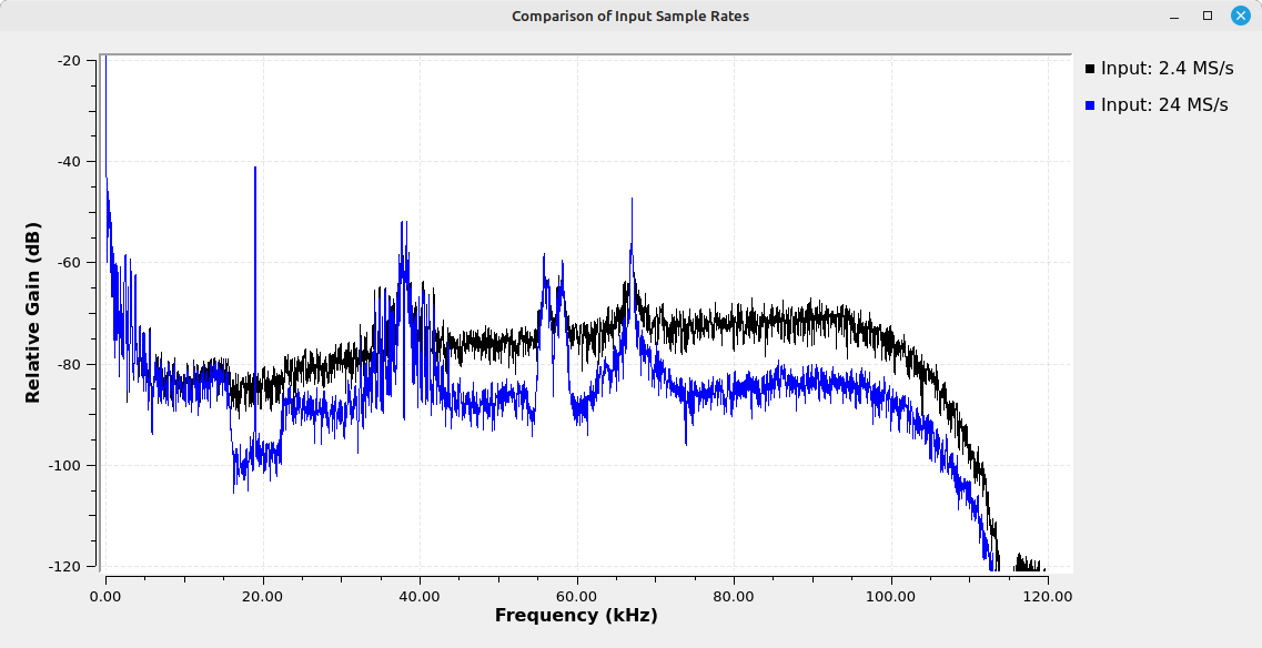
The result was an almost perfect demodulation. The baseband audio sounded perfect, with none of the crackling of the original circuit. The circuit is also quite simple. It takes a delay, a multiply, a "Multiply Const" (which could be replaced with a block that just flips the sign of the input sample), and the "Binary Slicer" block (which just looks at the sign of the input sample). The downside is that the circuit requires a much higher sample rate than the bandwidth of the signal should require. Further, the higher the sample rate, the better the final signal. Here's a spectral comparison of the modified circuit between a sample rate of 2.4 MS/s and 24 MS/s. Note that the latter shows a much better signal-to-noise ratio (SNR).
Finally, here's how the audio sounds using a 2.4 MS/s input in this modified circuit.
| This is the demodulated audio from an FM broadcast station using the modified pulse counting GRC graph above. |
Your question might be, "Can I get an even better SNR with a higher sample rate?" Possibly, but you'll reach a point of diminishing returns. Further, based on a very simple comparison, this circuit is still not as good as a polar discriminator. As a matter of fact, the best that this circuit could be would be equivalent to that of a polar discriminator.
Differences of Hardware and Software Radios
I came across a tweet a few weeks back that struck me. If you're thinking, "These don't look the same.", you're correct. They're not the same. The one on the right is better.

To be fair, these are not equivalent. The system on the left is a complete system. It's a Grundig Music-Boy Deluxe radio receiver. It has its own power supply (mains or batteries), antenna, demodulator, audio speaker, and the knobs and buttons necessary to control it. This particular receiver can be used to demodulate and recover AM or FM audio signals over several ranges. Its operation takes nothing more than providing power (adding batteries, plugging into mains), extending the antenna, turning the unit on, and tuning to a RF transmission. Once a station is tuned in, the system takes care of the rest. This includes filtering the station, demodulating, and inputting the demodulated audio to the speaker. The user only has to choose the band (using the switches on top), tune to a station (using the large knob on the right), and setting the volume (using the left-most knob). That's it. According to this schematic of the Music Boy Deluxe, it covers the following ranges:
- LW (longwave): 145 - 260 kHz
- MW (midwave): 510 - 1620 kHz
- SW (shortwave): 5.92 - 6.2 MHz
- FM broadcast: 87 - 104 MHz
On the right, we have an unknown software defined radio (SDR). I'm guessing its some SDR that covers various parts of the HF region. Regardless, all we have is the part that tunes, converts the signal from real-to-complex, and digitizes. It doesn't have a power supply, processor, antenna, or speaker. It doesn't have any knobs, dials, switches or buttons that you can use to control it.
So, no, these are not equivalent. The Grundig radio is a complete receiver. The SDR is just a small piece of a complete software defined receiver.
Frankly, if you want a more equivalent picture, it would look something like this.
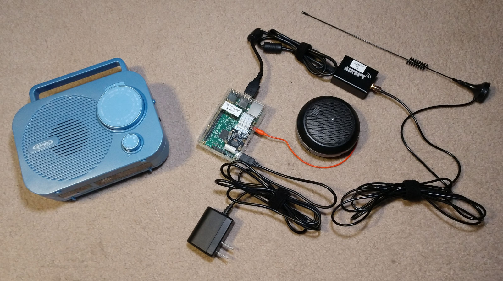
The picture above is a more apt comparison. I have a Jensen MR-550 AM/FM radio. It comes complete with a power supply and speaker to play the audio. On the right, I have an Airspy R2 SDR, a Raspberry Pi 3, a power supply for the Raspberry Pi, a JBL speaker, and an antenna.
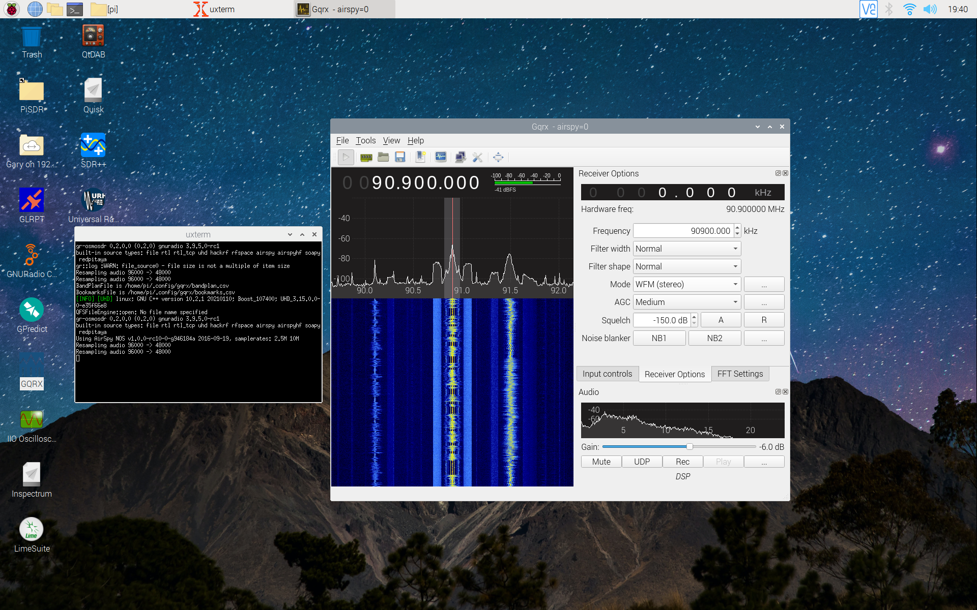
The description leaves out the most important part of the SDR, the software. It's a software defined radio, after all. With no software, it's just a tuner, quadrature demodulator and digitizer. In other words, a fancy paper weight. And a poor paper weight, at that. For this set-up, I decided to use "PiSDR". All I had to do was load the image onto a microSD card, load the card into the Raspberry Pi, and turn it on. After a quick set-up, I was up and running. The great thing was that all of the most popular SDRs are already set-up. This included RTL-SDR, HackRF, Airspy R2, SDRPlay, and LimeSDR.
To mimic the Grundig or Jensen radio, I simply used a FM broadcast station. I connected my Airspy R2 and the JBL speaker, fired up "GQRX" on the RPi, and tuned it to 90.9 MHz. The audio was perfect. The various components, working together, provided the same functionality as the Jensen radio.
So, that's it, right? Just put those components together and we have a system that's equivalent to our old hardware? In a word, nope. The system on the left can only handle analog AM and FM audio. That's it. The one on the right? It can handle more. A lot more. It has a much larger frequency range. This includes being able to use a larger variety of antennas since all the SDRs use a standard connector, such as SMA or MCX. It can be set for a much larger number of bandwidths. It can not only demodulate audio, it can also provide several types of displays, including time domain (aka "oscilloscope"), frequency domain (aka "spectrum analyzer") and even IQ polar plots. It can also demodulate and decode various digital systems, so long as the software (and the processing hardware) supports it. It can display video of different types, both analog and digital.
So, yeah, the original comparison is apt. The poster was trying to show the improvement in radio receivers. It wasn't really an accurate comparison because the hardware shown was wrong. But given that it's the software that's really crucial here, that would have been more difficult to show. (How much would a screenful of C++ or Python code show you?) The radio on the right is definitely an improvement. A vast improvement.
Appendix: Loading PiSDR Image
As part of the research for this post, I loaded "PiSDR" onto one of my RPi 3 Model B's microSD cards. It turns out it wasn't that straightforward. I never got RPi's image writer to work. It kept writing the image, then saying that the "verify" operation didn't work. I finally gave up and went through the steps outlined below. These steps worked. NOTE: My specific system is Linux Mint 21 running on an Intel i7-6700 processor.
- Download the PiSDR image. This will be a file with the ending ".img.xz". It's an image file that has been compressed.
- Uncompress the image file using the "unxz" command from the command line. An example is: unxz 2022-01-07-PiSDR-vanilla.img.xz (NOTE: The output will be an ".img" file.)
- Use a standard writer tool, such as Linux Mint's "USB Image Writer", to write the ".img" file to your microSD card. NOTE: The microSD should be at least 16 GB. The image file, once uncompressed, is 8.6 GB.
While RPi's image writer didn't work, the steps above did. Once I had the image written, I plugged the microSD card into my Pi, powered it up, and it worked perfectly.