
Random Quote Board
Understanding the Bandwidth Limits of a Tayloe Detector
UPDATE: In the first iteration of this post, I stated that a Tayloe detector combines real-to-complex conversion and analog-to-digital conversion. This is incorrect. A Tayloe detector only performs real-to-complex conversion; a separate ADC is required for each of the in-phase (real) and quadrature (imaginary) streams, just as with a quadrature demodulator. Sorry about that, Chief.
Here's the problem, as I see it. There are two methods to convert real samples into complex samples. These are the quadrature demodulator and the Tayloe detector. The most common method is with the quadrature demodulator. But the Tayloe detector is a much simpler circuit.
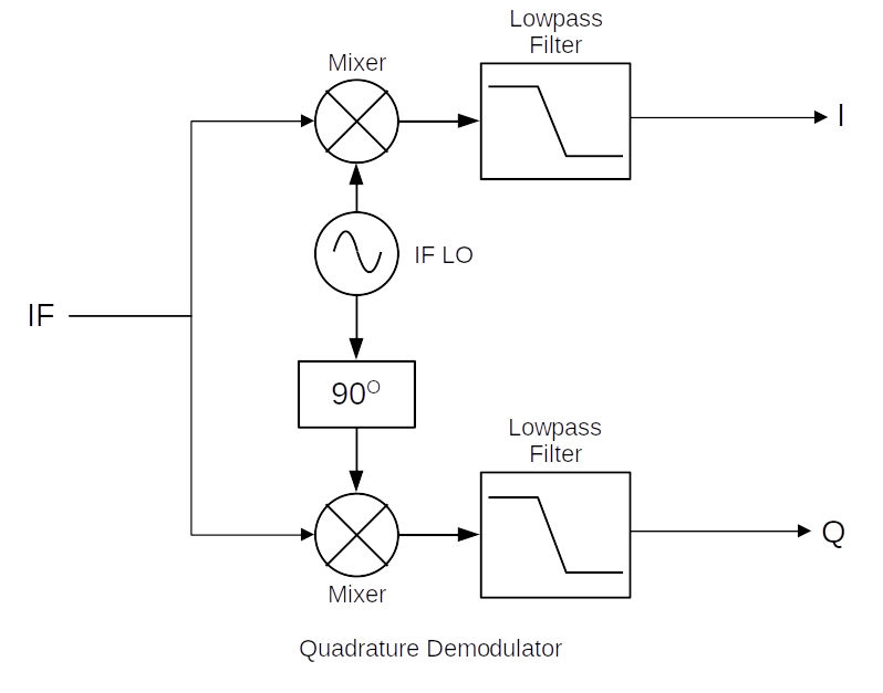
So why is the Tayloe detector not the most common method, given its simplicity? In a word, bandwidth. The Tayloe detector has a problem. Yes, it converts real samples to complex ones. But it does not do so perfectly. The whole concept of quadrature signals is that you have two signals, one in-phase (I) and one quadrature (Q) that are 90o out of phase with each other. If they're not exactly 90o out of phase with each other, then they're not actually in quadrature. You can get away with some loss of quadrature. But there's a price to pay. As the phase difference between the I & Q streams moves away from 90o, it moves towards a purely real signal.
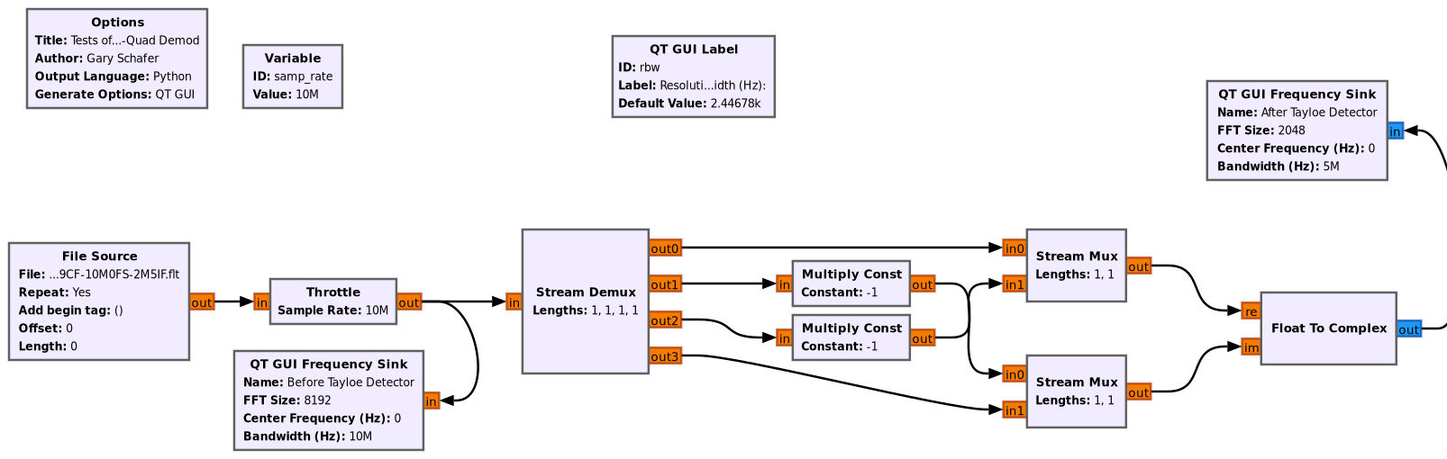
To better understand this, I created a circuit in Gnu Radio Companion (GRC) that mimics a Tayloe detector.
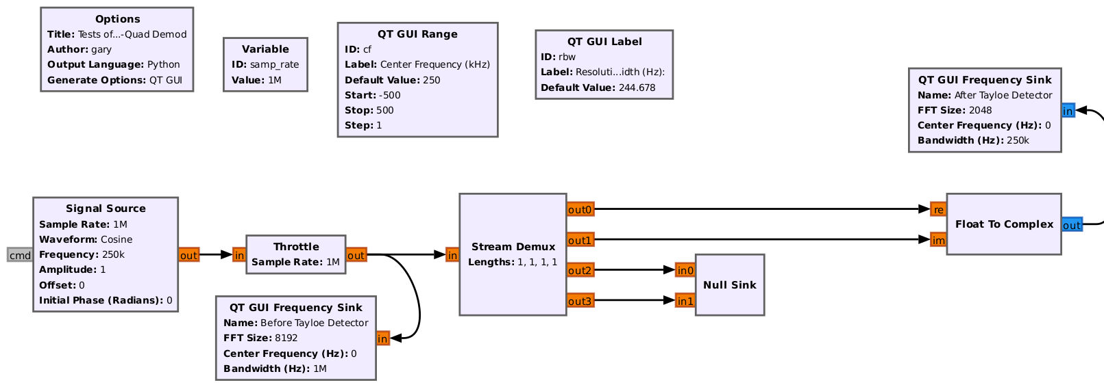
The input to the Tayloe detector is a sinewave. The sample rate is 1 MHz. This means that the input signal should be at 1/4 of this, or 250 kHz. The initial frequency is right at 250 kHz. The output spectrum is a single spectral line right at 0 Hz. But what happens if we change the input frequency? For example, setting the input frequency from 250 kHz to 249 kHz?
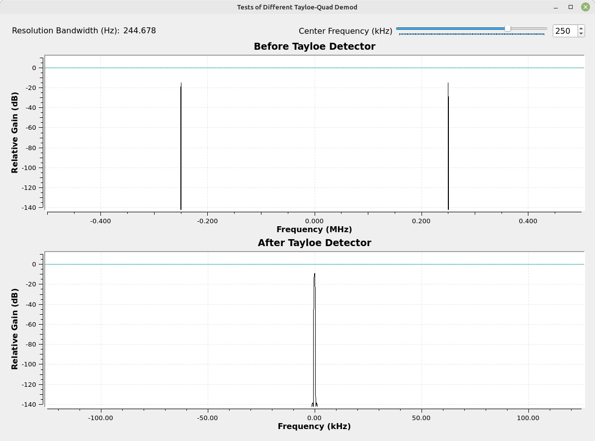

With an input frequency that is offset from 1/4 of the Tayloe detector clock rate, the output is not the one spectral line of a true quadrature sinusoid, but two spectral lines. Note that they're not at the same amplitude as they would be if they were completely real. It's somewhere between real and true quadrature.
Why does this happen? What's going on? Let's digress here for a moment to ensure everyone understands the practical differences between a real and complex signal. I'm going to use a basic sinewave as my example. Also, I'm going to use a double-sided spectrum so that everyone understands the spectral difference.
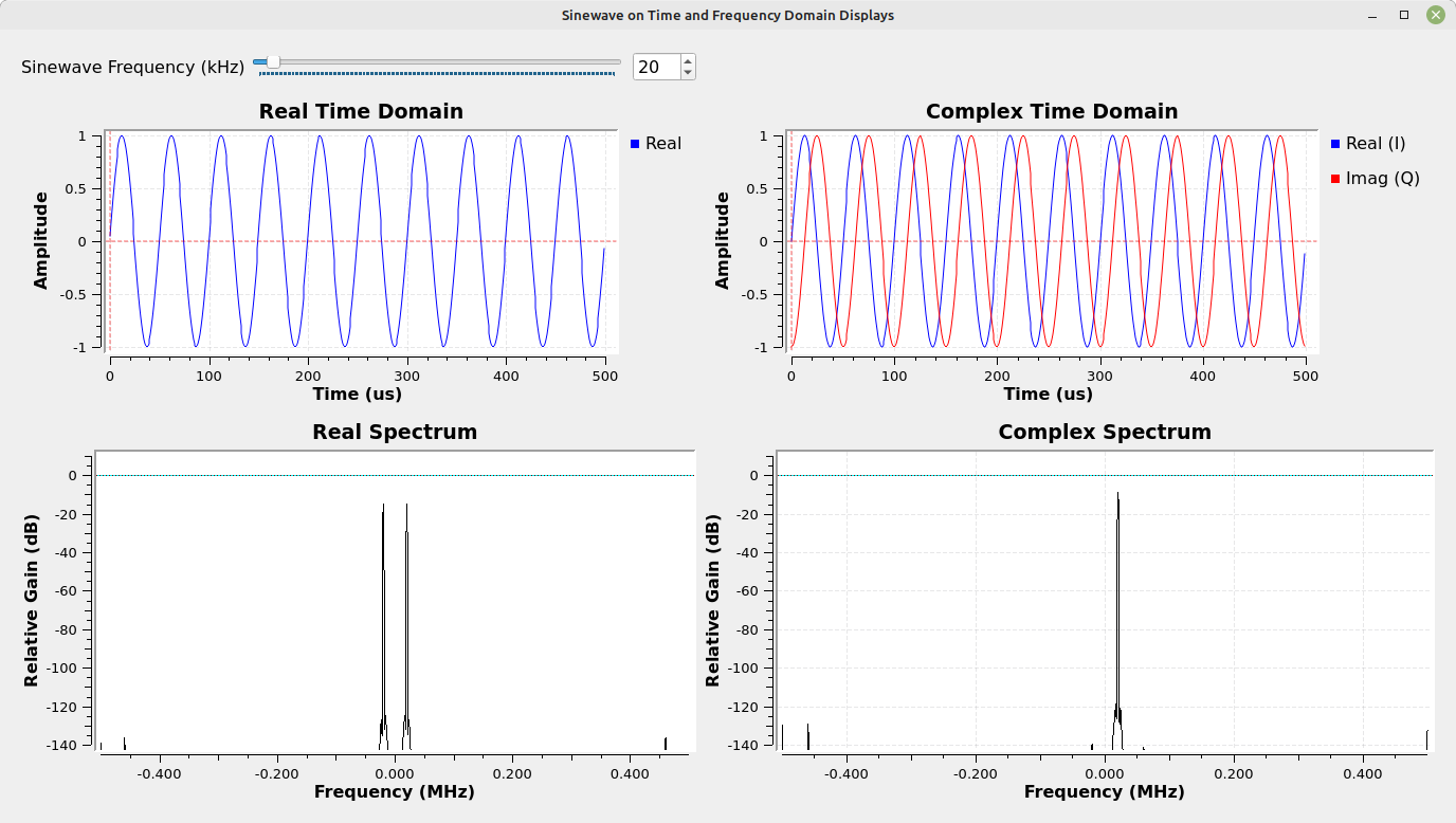
A real sinewave (meaning one that has no imaginary component) will display two spectral lines. One spectral line will be at its positive frequency; the other will be at its negative frequency. These spectral lines are mirror images of each other. A complex sinusoid, on the other hand, will only show a single spectral line. The mirror image spectral line is cancelled out due to the fact that the two sinusoids, one real and one imaginary, are precisely in quadrature (90o out of phase with each other).
What happens if they're not precisely in quadrature, though? I've created a flowgraph that allows you to adjust the phase between the real and imaginary parts of a complex sinusoid. It allows you to see the effect of having the sinusoids not being perfectly in quadrature.
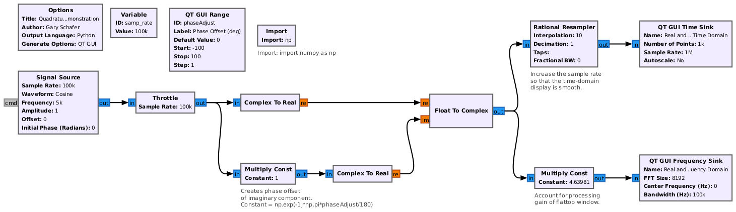
Running this flowgraph and then adjusting the phase offset between the real and imaginary components, which creates what is called "IQ imbalance", we can see that the mirror image is no longer perfectly cancelled out.

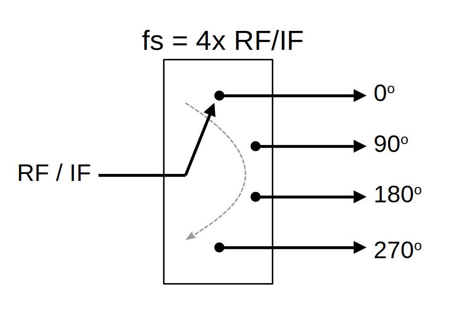
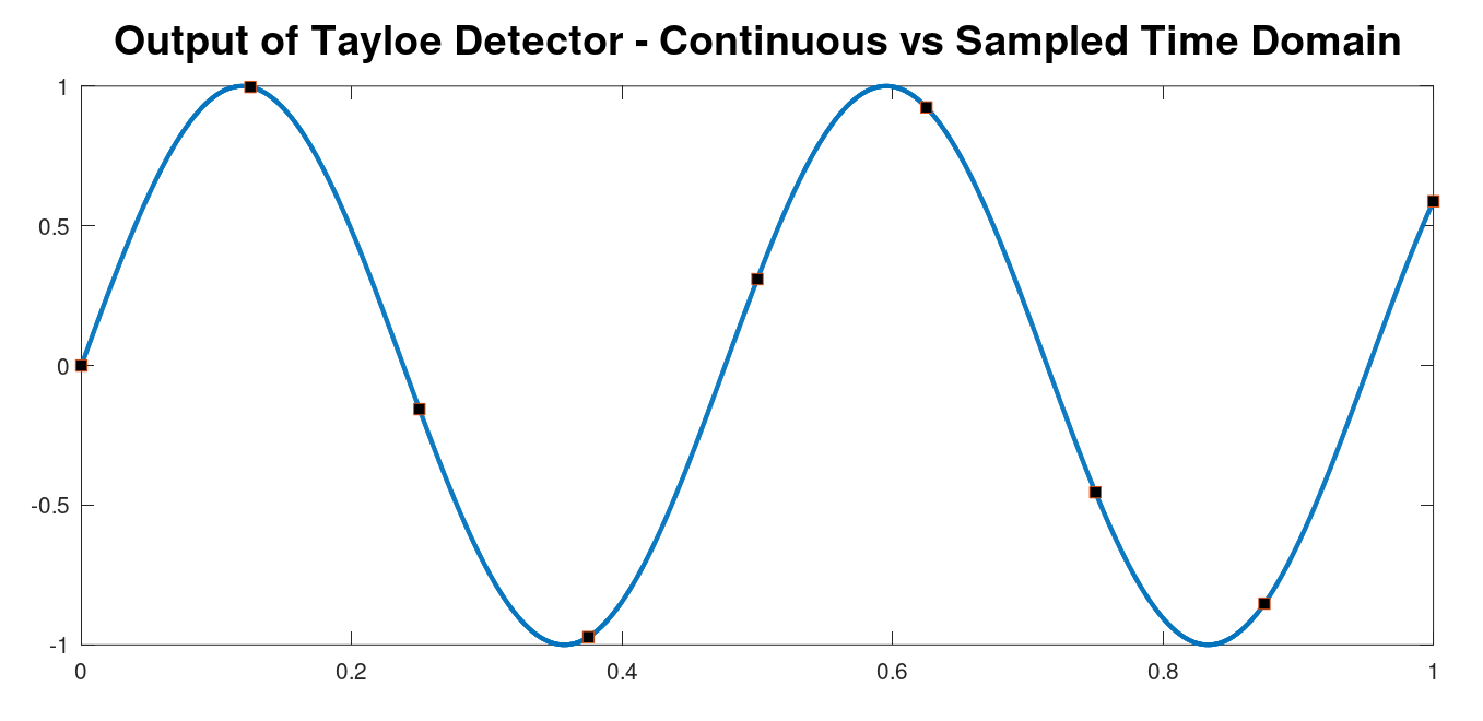
The reason we get the output we do is because if the signal is not centered, we wind up with IQ imbalance. And why is that? If we look at the sampled waveform at the output of the Tayloe detector, and compare it to the continuous waveform, we can see that the samples no longer line up with a 90o phase offset. The Tayloe detector samples at 4 points, but those are tied to the clock of the Tayloe circuit. Therefore, you only get a 90o phase offset when the signal is precisely at 1/4 of this clock rate. Any frequency higher or lower will not be. Hence, IQ imbalance.

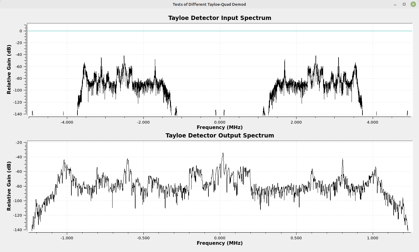
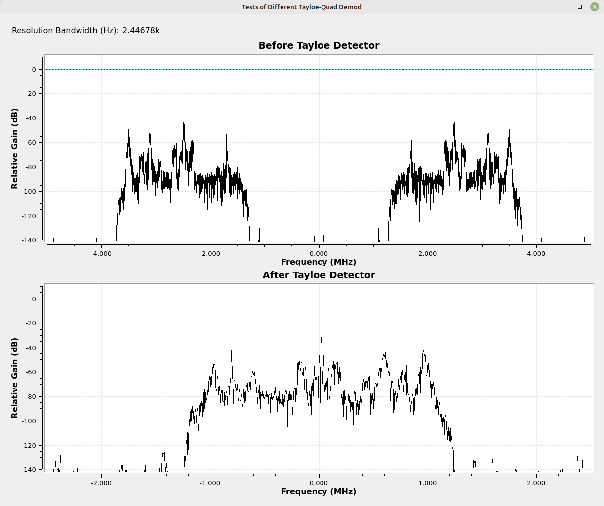
What does this mean from a practical standpoint? I changed the Tayloe detector circuit so that the input was a portion of actual spectrum. I used 2.5 MHz of spectrum from the FM band. The input is a real signal centered at 2.5 MHz with a 10 MHz sample rate. The output is a (partially) quadrature signal.
Now, the question becomes, how bad is this problem? Is there some way to quantify it? Using the Tayloe detector circuit with the sinewave input, it's possible to measure the level of the mirror image spectral line relative to the desired signal level. Using a ratio of offset relative to the Tayloe detector sample rate, here's a short table showing the amplitude of the mirror image relative to the desired signal level. As an example, if the initial sample rate is 1 MHz and the frequency offset from center is 1 kHz, then this is an offset ratio of 0.001 (1 kHz / 1 MHz).
| Offset Ratio | Relative Amplitude (linear) | Relative Amplitude (dB) |
|---|---|---|
| 0.0 | 0 | -∞ |
| 0.001 | 3.16e-3 | -50.1 |
| 0.002 | 6.61e-3 | -43.6 |
| 0.005 | 16.2e-3 | -35.8 |
| 0.01 | 31.3e-3 | -30.1 |
| 0.02 | 63.1e-3 | -24.0 |
| 0.025 | 78.5e-3 | -22.1 |
| 0.05 | 160e-3 | -15.9 |
| 0.125 | 383e-3 | -8.4 |
A ratio of 1 equals 0 amplitude. A ratio of 0.5 equals an amplitude of 1. Trying a few combinations, I determined that a (perhaps rough) approximation is:
Relative amplitude = 20*log10(sin(Δratio*π))
I consider the mirror image to be interference. We can use this to determine the maximum bandwidth given the maximum amount of interference we want to deal with. For example, if the maximum interference level is -30 dB compared to the desired frequency, then working backwards, this equates to a delta ratio of 0.01. Thus, for a sample rate of 1 MHz, the maximum delta is 0.01 or 10 kHz. The bandwidth will be twice this (+/- this frequency), the maximum bandwidth will be 20 kHz. For a maximum interference level of -20 dB, the delta ratio works out to be approximately 0.032. Maximum bandwidth for a 1 MHz sample rate would be 64 kHz.
This leaves me with a few points. First, a Tayloe detector is a simple circuit. It's much easier to implement than a quadrature demodulator. Second, this simplicity comes with a cost, namely bandwidth. In order to achieve a high bandwidth, it's necessary to either put up with a fair amount of interference or its necessary to use a high clock rate in the Tayloe detector itself. Third, implementing the Tayloe detector without spectral inversion means that the imaginary segment needs to be conjugated. Otherwise, the spectrum will be inverted. Finally, it's possible to select a bandwidth at the output of the Tayloe detector that is either 1/2 or 1/4 of the Tayloe clock rate.
This final sample rate does not appear to affect the relative interference; it simply means that it's possible to downconvert and sample a larger bandwidth, so long as you're willing to accept the much higher interference levels.
If the bandwidth of a Tayloe detector is so relatively low, then why does it work so well for many people? My guess is that they're using it for relative low bandwidths, 20 - 40 kHz. Even a modest sample rate of 1 MHz would provide such bandwidths with tolerable interference levels.
There you have it. My (probably poor) explanation of the bandwidth limitations of a Tayloe detector. It's still a very useful circuit. Just understand its limits.